Vertical and axial suspension supporting structure

A support structure and vertical technology, applied in the field of vertical axial suspension support structure, can solve the problems of complex magnetic bearing technology, high cost, no application of amusement machine equipment, etc., and achieve simple structure, low production and use costs, The effect of reducing installation and maintenance links

Active Publication Date: 2016-03-23
GUANGDONG JINMA ENTERTAINMENT CORP LTD
View PDF7 Cites 0 Cited by
  • Summary
  • Abstract
  • Description
  • Claims
  • Application Information

AI Technical Summary

Problems solved by technology

However, the magnetic bearing technology is complicated, and the active magnetic bearing also involves a feedback control system, which is costly and has no application in amusement machine equipment at present.

Method used


Image

  • Vertical and axial suspension supporting structure
  • Vertical and axial suspension supporting structure
  • Vertical and axial suspension supporting structure

Examples


Embodiment Construction

[0027] A further detailed description will be made below in conjunction with the accompanying drawings and embodiments of the present invention:

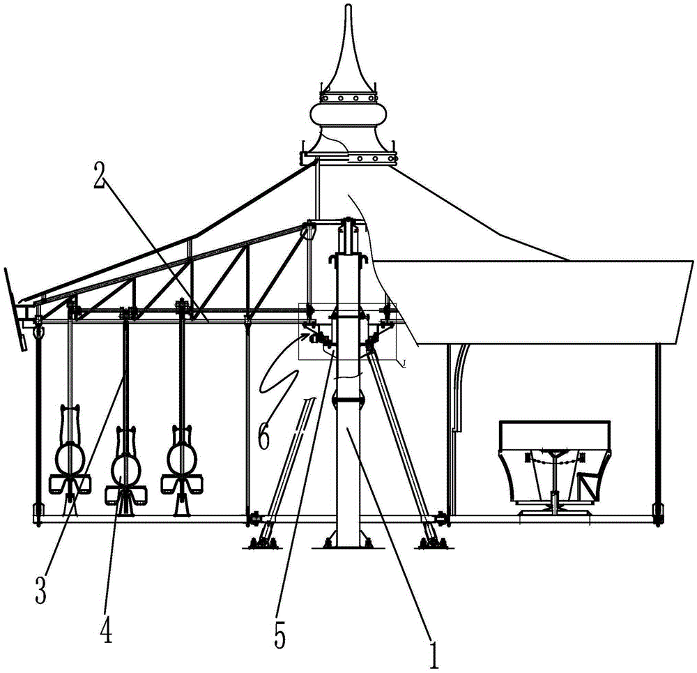
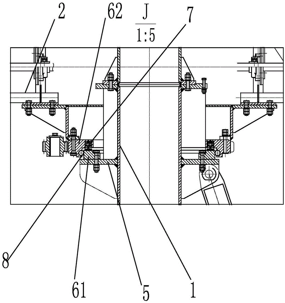
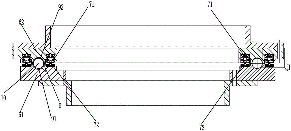
[0028] Such as Figure 1-9 , the present invention discloses a vertical axial suspension support structure, comprising a vertically arranged column 1, a turntable 2 capable of horizontally rotating relative to the column 1 is mounted on the column 1, and a mounting seat 5 is provided on the outer wall of the column 1, Between the mounting base 5 and the turntable 2, there is a magnetic levitation rotary support device 6 arranged horizontally. The transverse annular upper ring 62, the transverse annular lower ring 61 and the transverse annular upper ring 62 are separately arranged, and the transverse annular lower ring 61 and the transverse annular upper ring 62 are all sleeved outside the column 1, and are arranged on the column 1 during work. The upper motor drives the transverse annular upper ring 62 to rotate through the driving...


PUM


Abstract

The invention discloses a vertical and axial suspension supporting structure. The vertical and axial suspension supporting structure comprises a stand column arranged vertically. Rotating discs capable of rotating horizontally are installed on the stand column. Installing bases are arranged on the outer wall of the stand column. Magnetic levitation rotation supporting devices arranged horizontally are arranged between the installing bases and the rotating discs. Each magnetic levitation rotation supporting device comprises a transverse annular lower ring fixedly connected with the corresponding installing base and a transverse annular upper ring fixedly connected with the corresponding rotating disc. Magnetic levitation devices are arranged between the transverse annular lower rings and the transverse annular upper rings and capable of forming magnetic levitation acting force between the transverse annular lower rings and the transverse annular upper rings. Radial positioning devices capable of preventing the transverse annular upper rings from shifting in the radial direction are further arranged between the transverse annular lower rings and the transverse annular upper rings. The radial positioning devices comprise transverse annular guide rails arranged on the transverse annular lower rings and / or the transverse annular upper rings. A plurality of limiting balls are arranged in the transverse annular guide rails. The vertical and axial suspension supporting structure is simple in structure, convenient to maintain, permanent in magnetic levitation and small in power consumption.

Description

[technical field] [0001] The invention relates to an amusement device, in particular to a vertical axial suspension support structure. [Background technique] [0002] At present, ordinary slewing bearings or bearings are widely used in slewing mechanisms. Ordinary slewing bearings or bearings are common: outdoor use, rain and sun exposure, dusty, harsh natural environment, large rigid connection impact, difficult maintenance (working at heights), and relatively large frictional resistance. The non-mechanical contact magnetic bearing has the advantages of non-contact, no lubricant, low power consumption, adjustable bearing damping and rigidity, etc., and can meet the special use occasions of amusement equipment. However, the magnetic bearing technology is complicated, and the active magnetic bearing also involves a feedback control system, which is expensive and has no application in amusement machine equipment at present. [Content of the invention] [0003] The invention...

Claims


Application Information

Patent Timeline
IPC IPC(8): F16C32/04A63G1/00
Inventor 刘喜旺黄荣义
Owner GUANGDONG JINMA ENTERTAINMENT CORP LTD
Why Eureka
Try Eureka