Ball valve with non-contact valve ball and valve seats during rotation

A non-contact, valve seat technology, applied in the field of hydraulic components, can solve problems such as damaged parts, little effect, valve seal failure, etc., to achieve the effects of reducing resistance, simple manufacturing, and eliminating friction

Inactive Publication Date: 2016-03-23
YUEYANG DONGFANG AUTOMATIC CONTROL ENG EQUIP
View PDF5 Cites 7 Cited by
  • Summary
  • Abstract
  • Description
  • Claims
  • Application Information

AI Technical Summary

Problems solved by technology

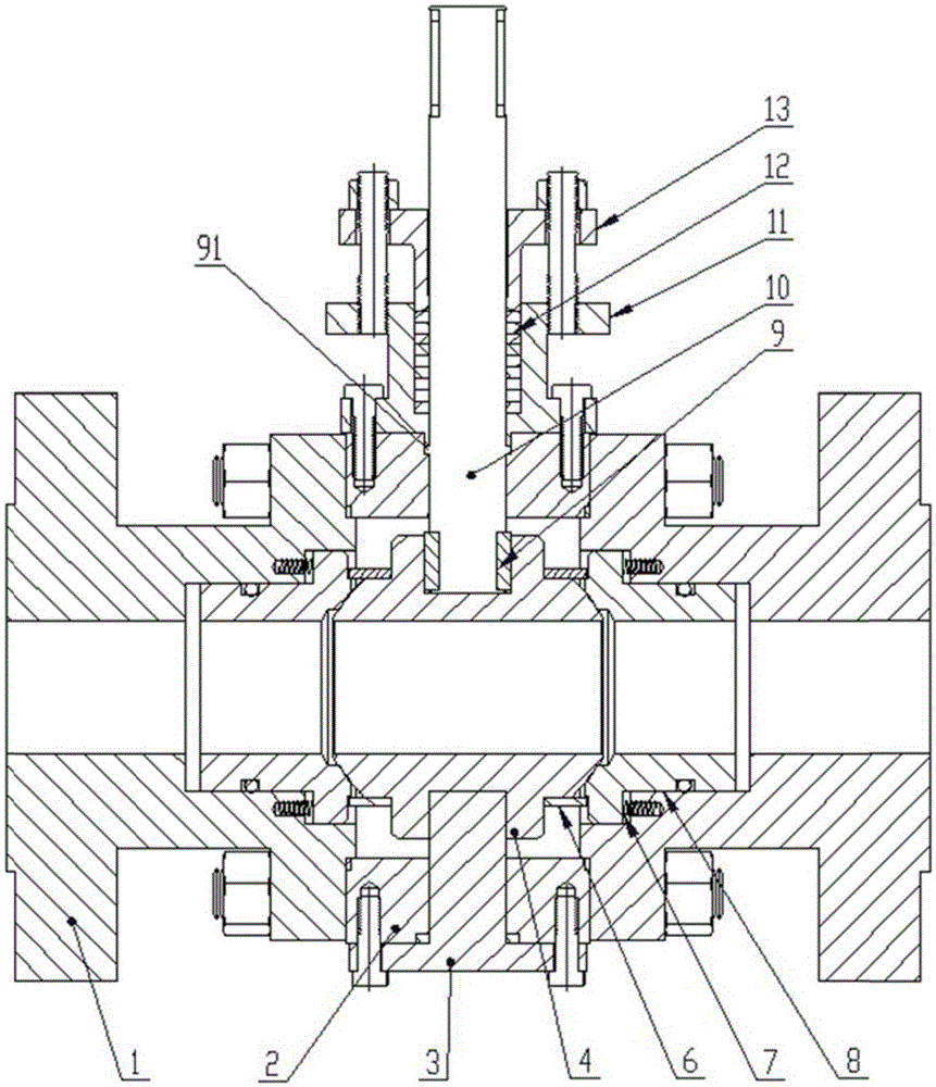
[0004] When the valve is opened or closed, the ball rotates, and the valve seat presses the ball under the action of fluid pressure difference and spring preload, and a large friction force is generated between the ball and the contact surface of the valve seat. This friction makes the ball The spherical surface and the sealing surface of the valve seat wear and damage the parts, which eventually leads to the sealing failure of the valve and causes the rotation of the ball 4 to generate a large frictional torque
[0005] In order to reduce this friction, it is generally used to spray expensive, high-strength wear-resistant alloy on the surface of the ball and the sealing surface of the valve seat or to improve the machining accuracy, but this method has little effect

Method used


Image

  • Ball valve with non-contact valve ball and valve seats during rotation
  • Ball valve with non-contact valve ball and valve seats during rotation
  • Ball valve with non-contact valve ball and valve seats during rotation

Examples


Embodiment Construction

[0040] The technical solutions of the present invention will be clearly and completely described below in conjunction with the accompanying drawings. Apparently, the described embodiments are some of the embodiments of the present invention, but not all of them. Based on the embodiments of the present invention, all other embodiments obtained by persons of ordinary skill in the art without making creative efforts belong to the protection scope of the present invention.

[0041] In the description of the present invention, it should be noted that the terms "center", "upper", "lower", "left", "right", "vertical", "horizontal", "inner", "outer" etc. The indicated orientation or positional relationship is based on the orientation or positional relationship shown in the drawings, and is only for the convenience of describing the present invention and simplifying the description, rather than indicating or implying that the referred device or element must have a specific orientation, ...


PUM


Abstract

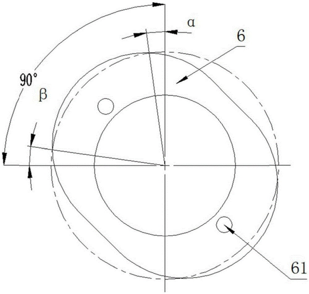
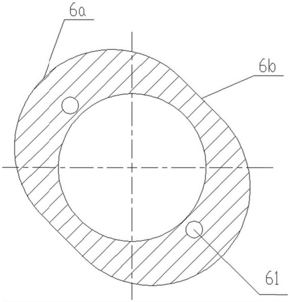
The invention provides a ball valve with non-contact valve ball and valve seats during rotation. The ball valve comprises a valve body, a ball body arranged in the valve body, a valve rod fixedly connected with the ball body to drive the ball body to rotate, two cam plates and two valve seats, wherein the two valve seats are correspondingly arranged at a first side and a second side of the ball body; and the two cam plates are correspondingly arranged at a third side and a fourth side of the ball body, and each cam plate is fixedly connected with the ball body and extends towards the corresponding valve seat, so as to separate the corresponding valve seat from the ball body. According to the invention, the cam plates are additionally arranged between the valve seats and the ball body, when the valve rod is rotated to rotate the ball body, the two valve seats located at the first side and the second side of the ball body are ejected away by the cam plates fixed at the third side and the fourth side of the ball body, the valve seats do not contact with the ball body during the rotation of the ball body, and a friction force between the spherical surface of the ball body and the sealing surfaces of each valve seat is avoided, thus the harmful friction force between the ball body and each valve seat during the rotation of the ball body is fundamentally eliminated.

Description

technical field [0001] The invention relates to the technical field of hydraulic components, in particular to a ball valve seat rotation non-contact ball valve. Background technique [0002] The trunnion ball valve is one of the most widely used valves in industry. In the fixed ball valve, the ball has a valve stem and a support shaft, both of which are fixed on the valve body, the position of the ball is fixed, and the fluid pressure cannot make it move. There are valve seats on both sides of the ball, and the valve seat is pressed against the ball by means of the spring and the thrust of the fluid to establish a sealing specific pressure. [0003] The main function of this valve is to cut off or connect the fluid channel in the pipeline, apply a certain torque on the valve stem with the help of the handle or driving device and transmit it to the ball to make it rotate 90 degrees, the through hole of the ball and the channel of the valve body The center lines are coincide...

Claims


Application Information

Patent Timeline
Patent Type & Authority Applications(China)
IPC IPC(8): F16K5/06F16K5/08F16K5/20F16K41/02
CPCF16K5/0605F16K5/0694F16K5/08F16K5/201
Inventor 吴军刘新学
Owner YUEYANG DONGFANG AUTOMATIC CONTROL ENG EQUIP
Why Eureka
Try Eureka