
A Downward Reflecting Solar Concentrating Heat Collector

A heat collecting device and solar energy technology, applied in the field of solar energy utilization, can solve the problems of difficult heat storage, large floor space, complex device structure, etc., to reduce heat collection loss, reduce high temperature heat storage, and simplify heat transfer process. Effect

Inactive Publication Date: 2018-04-17
CHINA UNIV OF PETROLEUM (EAST CHINA)
View PDF7 Cites 0 Cited by
  • Summary
  • Abstract
  • Description
  • Claims
  • Application Information

AI Technical Summary

Problems solved by technology

[0003] The existing dish-type solar heat-collecting device uses a rotating parabolic mirror to focus the sunlight on its focus, and the solar receiver is placed on the focus of the rotating parabolic mirror to absorb heat; however, the dish-type solar heat-collecting device exists The following disadvantages: Since the solar receiver in the dish solar collector is placed at the focus of the rotating parabolic mirror, the solar receiver needs to rotate with the rotating parabolic mirror to track the sun, so it is difficult to store heat
[0004] The existing literature (patent number: ZL201210016607.X) proposes a solar focusing high-temperature heat collection device at the bottom of the reflecting tower. The device uses multiple heliostats to focus and reflect sunlight to the top of the reflecting tower, and then uses Mirrors, conical mirrors, inverted compound parabolic mirrors, cylindrical mirrors and compound parabolic mirrors reflect the sunlight from the top of the tower to the solar receiver at the bottom of the tower to realize heat collection, heat storage and heat exchange at the bottom of the tower; However, the device has a complex structure and a large footprint, and is suitable for large-scale heat collection

Method used


Image

  • A Downward Reflecting Solar Concentrating Heat Collector
  • A Downward Reflecting Solar Concentrating Heat Collector
  • A Downward Reflecting Solar Concentrating Heat Collector

Examples


Embodiment Construction

[0017] The present invention will be further described below in conjunction with the accompanying drawings and embodiments.

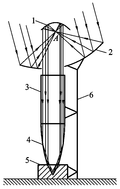
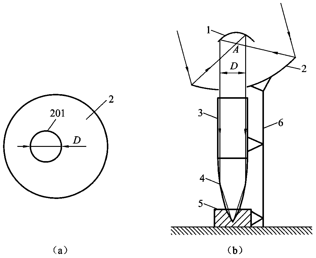
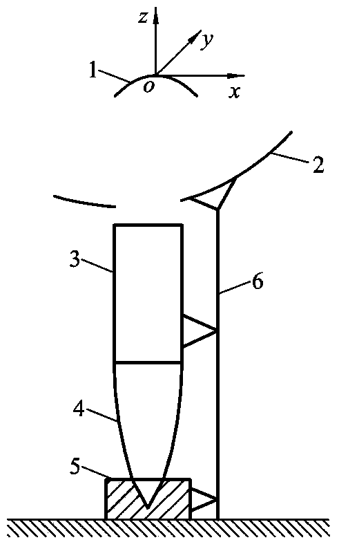
[0018] Such as figure 1 Shown is a diagram of the proposed downward-reflecting solar energy concentrating heat collector, including a rotating parabolic mirror (1), a rotating parabolic heliostat with a transmission hole (2), a cylindrical mirror (3), and a compound paraboloid mirror (4), sunlight receiver (5) and support frame (6); the rotating parabolic mirror (1) is placed upside down on the rotating parabolic heliostat (2) with a transmission hole, so that the rotating parabolic mirror (1 ) is vertically downward, so that the focus of the rotating parabolic mirror (1) and the rotating parabolic heliostat with a transmission hole (2) coincide; the cylindrical mirror (3), the compound parabolic mirror (4) and the sunlight The receiver (5) is placed directly below the transmission hole (201) of the rotating parabolic heliostat (2) with the transmissio...


PUM


Abstract

The present invention proposes a downwardly reflecting solar energy focusing heat collection device, comprising: a rotating parabolic mirror (1), a rotating parabolic heliostat with a transmission hole (2), a cylindrical mirror (3), and a compound parabolic mirror (4) , sunlight receiver (5) and support frame (6); the rotating parabolic mirror (1) is inverted and placed on the rotating parabolic heliostat (2) with a transmission hole, the cylindrical mirror (3), the compound paraboloid The mirror (4) and the sunlight receiver (5) are placed directly below the transmission hole (201) of the rotating parabolic heliostat (2) with the transmission hole; The heliostat (2) is reflected on the inverted rotating parabolic mirror (1), and then reflected downwards by it into a parallel beam passing through the transmission hole (201) to the compound parabolic mirror (4) directly below it, and finally reflected On the solar heat collector (5), realize the downward focusing reflection of sunlight.

Description

technical field [0001] The invention belongs to the technical field of solar energy utilization, and in particular relates to a downward-reflecting solar energy focusing heat-collecting device. Background technique [0002] Solar energy has the advantages of being clean, non-polluting, available anywhere, and inexhaustible, so the development, utilization and conversion of solar energy has become a hot spot of concern; in the utilization technology of solar energy, photothermal conversion technology is widely used , it converts solar radiation energy into thermal energy and utilizes it; at present, the low-temperature thermal utilization of solar energy is developing rapidly, such as solar water heaters; and the high-temperature thermal utilization technology of solar energy has very broad application prospects, such as solar thermal power generation and high-temperature heating, so It is of great significance to study new solar high-temperature heat collectors to improve th...

Claims


Application Information

Patent Timeline
Patent Type & Authority Patents(China)
IPC IPC(8): F24S23/70F24S23/71F24S30/40
CPCF24S23/70F24S23/71F24S23/82F24S30/40F24S2023/872Y02E10/47
Inventor 王君申贝贝李雪琴王增丽
Owner CHINA UNIV OF PETROLEUM (EAST CHINA)
Learn More