Header body shell tube communication pressure-bearing heat exchanger

A heat exchanger and box technology, applied in the field of HVAC, can solve the instability of the welded connection structure of the heat exchanger of the cold fluid header, the inflexible setting and manufacture of the shell-side channel and the tube-side channel, and the inability to install vertically To achieve the effect of improving product quality, enhancing strength and rigidity, and facilitating vertical or horizontal installation

Active Publication Date: 2016-03-23
山东利能换热器有限公司
View PDF8 Cites 2 Cited by
  • Summary
  • Abstract
  • Description
  • Claims
  • Application Information

AI Technical Summary

Problems solved by technology

[0007] It can be seen from the above that the welded connection structure of the cold fluid header heat exchanger in the prior art is unstable or unreasonable or the cost is high
There are also defects that the four inlet and outlet pipe joints are installed on the header part at one end, and the shell and tube cannot be installed vertically, or the setting and manufacturing of the shell-side channel and the tube-side channel are not flexible enough, and the heat exchange area is small and the thermal efficiency is low.

Method used


Image

  • Header body shell tube communication pressure-bearing heat exchanger
  • Header body shell tube communication pressure-bearing heat exchanger
  • Header body shell tube communication pressure-bearing heat exchanger

Examples


Embodiment Construction

[0038] The present invention will be further described below in conjunction with the accompanying drawings and specific embodiments.

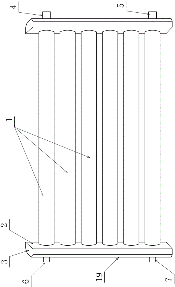
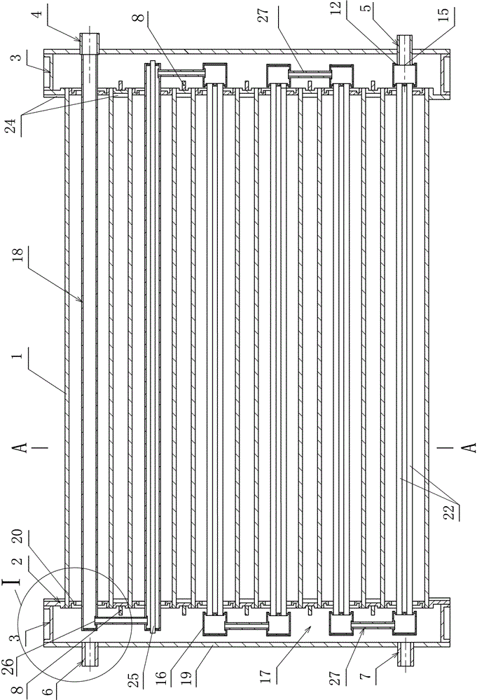
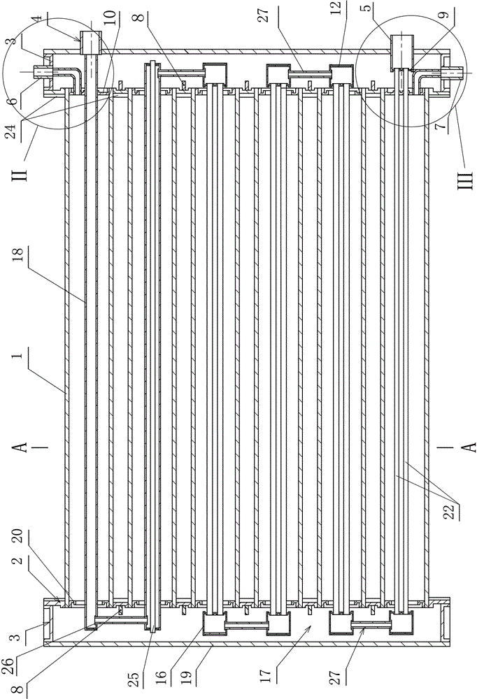
[0039] 1. A pressure-bearing heat exchanger connected by a header body shell tube of the present invention, such as Figure 1 to Figure 24 shown. It includes two header bodies, and the header body parts include: header inner orifice plate 2, header outer plate 19 and end cover plate 3; pipe joint installation holes 21 are opened on some parts of the header body, or the header body Pipe joint installation holes 21 are not opened on some components; pipe joints I7, pipe joints II6, pipe joints III4, and pipe joints IV5 are provided on some parts of the header body; Constitute a fluid circulation heat transfer flow channel; the space where the inner orifice plate 2 of the header is welded and combined with the outer plate 19 of the header is the inner chamber 17 of the header; the end cover plate 3 is sealed and welded to block the port of the he...


PUM


Abstract

The invention discloses a header body shell tube communication pressure-bearing heat exchanger. The header body shell tube communication pressure-bearing heat exchanger comprises two header bodies. Stiffening objects are arranged on the spacing board faces between header inner side pore plates and pipe holes of a plurality of shell circular pipes or / and circular ring stiffening plates are arranged in pipe openings of the multiple shell circular pipes. The stiffening objects are transversely welded to the header inner side pore plates to form T-shaped stiffening ribs. At least one pipe heat exchanging pipe or a combined heat exchanging pipe is arranged in each pipe cavity of the multiple shell circular pipes. The heat exchanging pipes or the combined heat exchanging pipes are held to bent pipes in inner cavities of headers to be communicated or be communicated by welding communication pipes. The inlet ends and the outlet ends of the heat exchanging pipes or the inlet ends and the outlet ends of the combined heat exchanging pipes are communicated by welding third pipe connectors and fourth pipe connectors to form pipe pass fluid circulation heat-transmission flowing channel. Two medium fluid in a heat exchanger passes through pipe passes of the heat exchanging pipes or the pipe passes of the combined heat exchanging pipes and / or the shell passes of the inner cavities of the headers and the shell passes of the multiple shell circular pipes to conduct heat exchanging. According to the header body shell tube communication pressure-bearing heat exchanger, the heat exchanging area is large, the header body shell tube communication pressure-bearing heat exchanger efficiency is high, and installation materials are saved.

Description

technical field [0001] The invention relates to the technical field of heating and ventilation, and relates to a heat exchanger for exchanging hot water by using heating air as a heat source, in particular to a pressure-bearing heat exchanger made of stainless steel or copper with a header body and a shell tube. Background technique [0002] The applicant filed an application on July 10, 2011. The name of the invention is "header pressure heat exchanger", the patent number is 201120255532.1, and the announcement number is CN202177324U. Applied on February 8, 2012, the name of the invention: "header double wall heat transfer edge welding heat exchanger", patent number: 201220040302.8, announcement number: CN202442615U. Applied on November 4, 2013, the name of the invention: "Multi-tube heat conduction heat exchanger for water storage heating with header and shell tube", patent number: 201320688555.0, announcement number: CN203605766U. [0003] The above-mentioned three prior...

Claims


Application Information

Patent Timeline
Patent Type & Authority Applications(China)
IPC IPC(8): F28D7/10F28F9/18
CPCF28D7/10F28F9/18
Inventor 张伟张冲
Owner 山东利能换热器有限公司
Why Eureka
Try Eureka