
Positron emission tomography (PET) detector, method for setting PET detector and detecting method thereof

A detector and sensor technology, applied in the field of light detection, can solve the problems of light transmission loss, low resolution of PET detectors, etc., and achieve the effect of flexible setting and cost reduction

Active Publication Date: 2016-03-23
SHANGHAI UNITED IMAGING HEALTHCARE
View PDF16 Cites 18 Cited by
  • Summary
  • Abstract
  • Description
  • Claims
  • Application Information

AI Technical Summary

Problems solved by technology

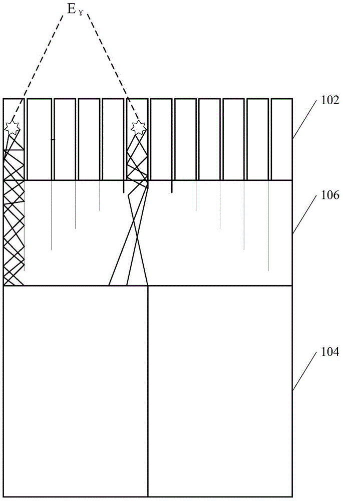
[0005] When the gamma ray excites photons inside the crystal unit, since the light guide plate 106 will cause a certain loss of light transmission, only part of the excited photons can enter the APD array 104, resulting in the resolution of the PET detector lower

Method used


Image

  • Positron emission tomography (PET) detector, method for setting PET detector and detecting method thereof
  • Positron emission tomography (PET) detector, method for setting PET detector and detecting method thereof
  • Positron emission tomography (PET) detector, method for setting PET detector and detecting method thereof

Examples


Embodiment Construction

[0059] Currently, in such figure 1 In the PET detector structure shown, after the γ-ray excites photons in the crystal unit, the photons enter the APD array 104 through the light guide plate 106 . Wherein, the arrangement of the light guide sheet 106 increases the distance of photon transmission, which causes a certain loss of light transmission, and reduces the resolution of the PET detector.

[0060] In order to make the above objects, features and advantages of the present invention more comprehensible, specific embodiments of the present invention will be described in detail below in conjunction with the accompanying drawings.

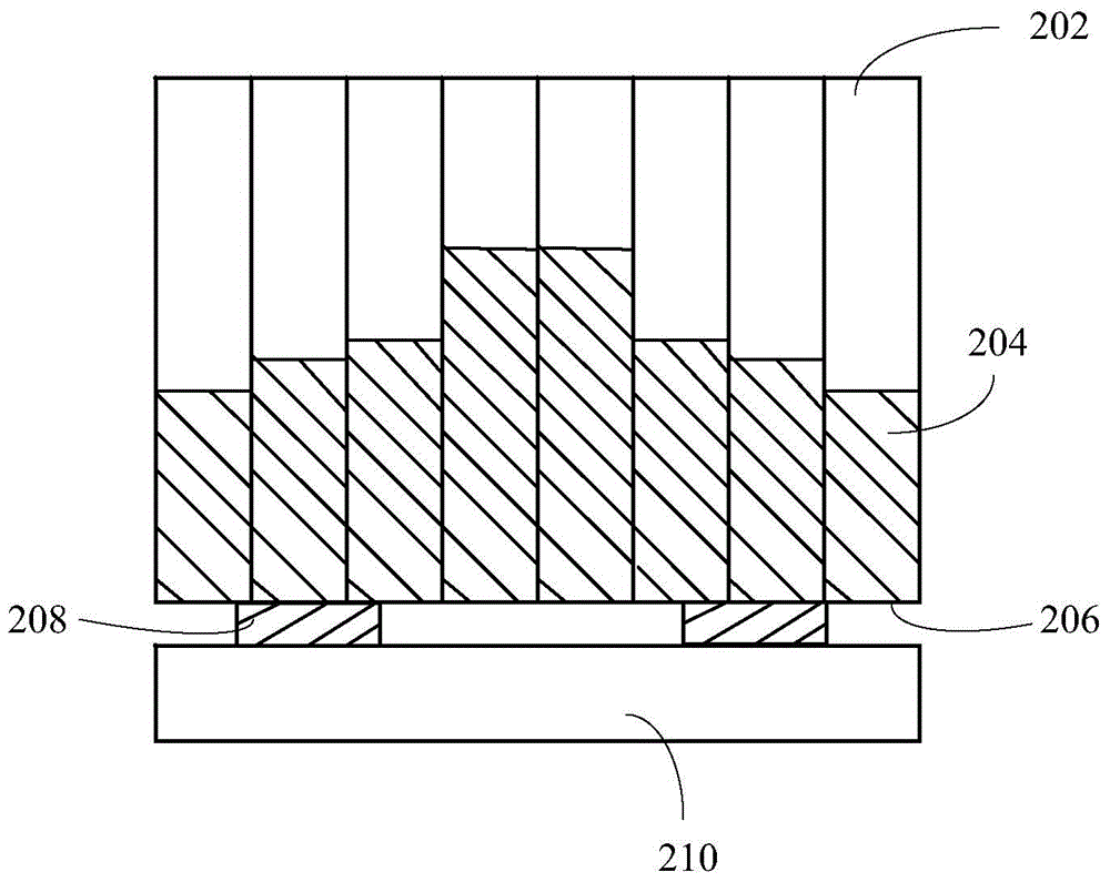
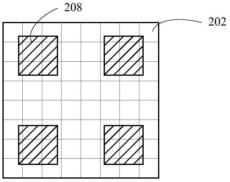
[0061] see figure 2 , an embodiment of the present invention provides a PET detector, and the PET detector may include: a crystal array and a semiconductor sensor array.

[0062] Wherein, the crystal array may include a plurality of crystal units 202 arranged in an array, and a light splitting structure 204 arranged on the surface of the crystal...


PUM


Abstract

The invention provides a positron emission tomography (PET) detector, a method for setting the PET detector and a detecting method thereof. The PET detector comprises the components of a crystal array which comprises a plurality of crystal units that are arranged in an array manner and light splitting structures that are arranged on the surfaces of the crystal units, wherein the light splitting structure define the light outlet surface of the crystal array; and a semiconductor sensor array which is arranged relative to the light outlet surface of the crystal array and is suitable for receiving photons from the light outlet surface, wherein the semiconductor sensor array comprises a plurality of semiconductor sensors which are arranged in an array manner. Through arranging the light splitting structures on the crystal units, an effect which is similar with the effect obtained through arranging a light guide plate between the crystal array and the semiconductor sensors is realized. The transmission distance of the photon can be effectively shortened, and furthermore light transmission loss caused by the light guide plate can be prevented, thereby improving resolution of the PET detector.

Description

technical field [0001] The invention relates to the technical field of light detection, in particular to a PET detector, a method for setting up the PET detector and a detection method. Background technique [0002] Positron Emission Tomography (Positron Emission Tomography, PET) detectors are usually set in various large-scale medical equipment using PET technology, for example: set in Positron Emission Tomography-Computed Tomography (Positron Emission Tomography-Computed Tomography, PET-CT ) equipment or positron emission tomography-magnetic resonance imaging (Positron Emission Tomography-Magnetic Resonance Imaging, PET-MRI) equipment. The PET detector is used to receive the gamma rays produced in the patient's body, and feed back the position information of the photons generated by the received gamma rays on the detector to other components of the large medical equipment, so that other components of the large medical equipment Corresponding processing is performed accord...

Claims


Application Information

Patent Timeline
IPC IPC(8): G01T1/24
Inventor 安少辉张强
Owner SHANGHAI UNITED IMAGING HEALTHCARE
Learn More