Optical connector and manufacturing method for optical connector
An optical connector and optical connection technology, which is applied in the coupling of optical waveguides, instruments, optics, etc., can solve the problem of optical characteristic degradation and achieve the effect of suppressing the decline of optical characteristics
- Summary
- Abstract
- Description
- Claims
- Application Information
AI Technical Summary
Problems solved by technology
Method used
Image
Examples
no. 1 Embodiment approach
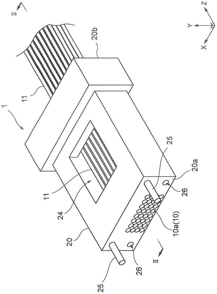
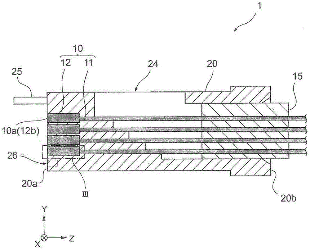
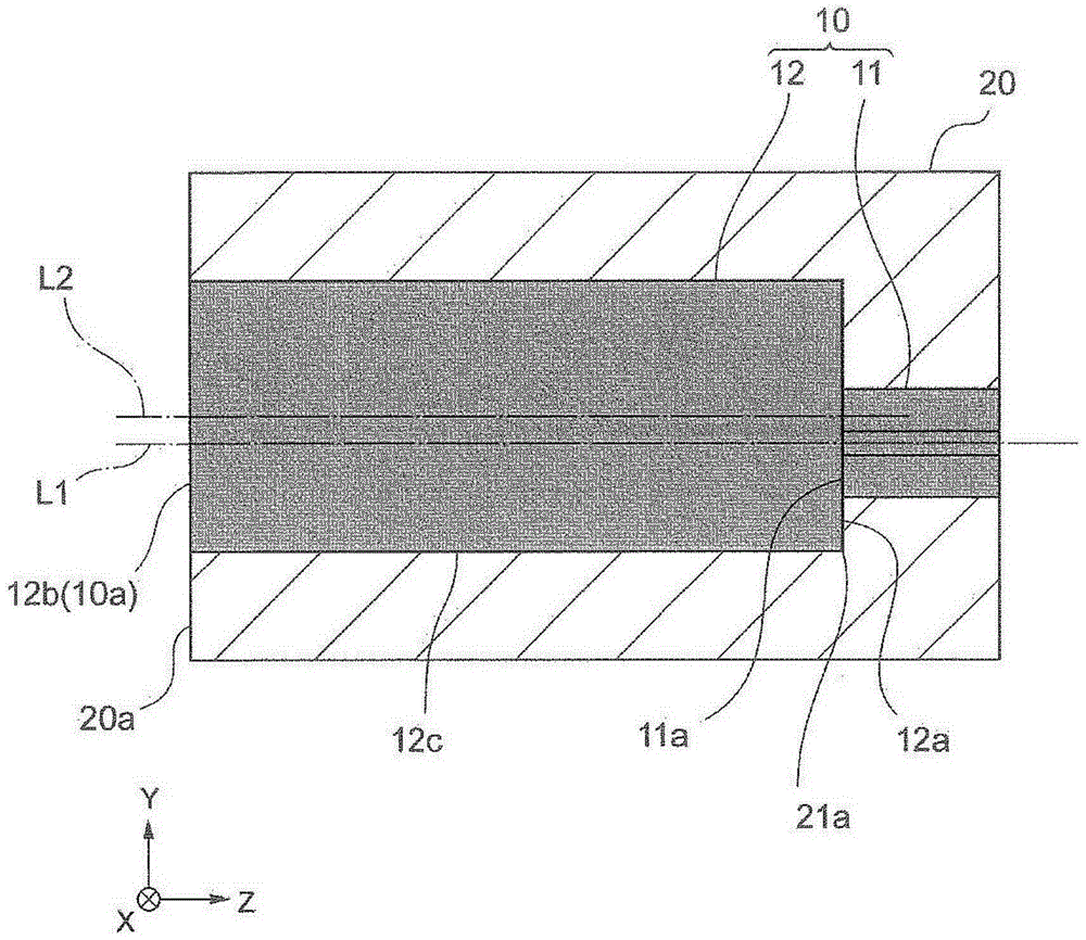
[0080] figure 1 It is a perspective view showing the optical connector according to the first embodiment of the present invention, figure 2 is along figure 1 The cross-sectional view of the optical connector shown in line II-II. image 3 will be figure 2 Part III shown enlarged while showing the figure, Figure 4 is along figure 2 The cross-sectional oblique view and partial enlarged cross-sectional oblique view of the ferrule on line II-II shown. Figure 5 It is a figure which schematically shows the coupling state (optical connection state) of the light incident / exit part concerning 1st Embodiment, Image 6 It is a figure which schematically shows the coupling state (optical connection state) of the optical connector concerning 1st Embodiment of this invention.
[0081] For convenience of explanation, an XYZ rectangular coordinate system is described in each figure. The X-axis extends along the long-side direction of the front end and the rear end of the incident / e...
no. 2 Embodiment approach
[0122] Figure 10 It is a perspective view showing the optical connector according to the second embodiment of the present invention, Figure 11 is along Figure 10 A cross-sectional view of an optical connector showing the XI-XI line. Figure 12 will be Figure 11 Part XII shown enlarged while showing the figure, Figure 13 is along Figure 10 A partially enlarged cross-sectional view (schematic diagram) of the light incident / exited part along line XI-XI shown. Figure 14 is along Figure 10 A partially enlarged cross-sectional oblique view of the ferrule of the XI-XI line shown. Figure 15 It is a figure which schematically shows the coupling state (optical connection state) of the light incident / exit part concerning 2nd Embodiment, Figure 16 It is a figure which schematically shows the coupling state (optical connection state) of the optical connector concerning 2nd Embodiment of this invention.
[0123] Such as Figure 10 and Figure 11 As shown above, the optic...
no. 3 Embodiment approach
[0137] Figure 17 It is a perspective view showing the optical connector according to the third embodiment of the present invention. Figure 18 It is a figure which schematically shows the coupling state (optical connection state) of the light incident / exit part concerning 3rd Embodiment, Figure 19 It is a figure which schematically shows the coupling state (optical connection state) of the optical connector concerning 3rd Embodiment of this invention.
[0138] Such as Figure 17 As shown, in the optical connector 1B according to the third embodiment, the structure of the guide portion is different from that of the optical connector 1A. Specifically, the optical connector 1B differs from the second embodiment in that the optical connector 1A includes a ferrule 20B instead of the ferrule 20A. Other configurations of the optical connector 1B are the same as those of the optical connector 1A.
[0139] The ferrule 20B differs from the ferrule 20A in that it includes one guide...
PUM
 Abstract
Description
Claims
Application Information
 - R&D
- Intellectual Property
- Life Sciences
- Materials
- Tech Scout
- Unparalleled Data Quality
- Higher Quality Content
- 60% Fewer Hallucinations
Browse by: Latest US Patents, China's latest patents, Technical Efficacy Thesaurus, Application Domain, Technology Topic, Popular Technical Reports.
© 2025 PatSnap. All rights reserved.Legal|Privacy policy|Modern Slavery Act Transparency Statement|Sitemap|About US| Contact US: help@patsnap.com


