Optical system of airborne star sensor

An optical system and star sensor technology, applied in the field of star sensors, can solve the problems of large distance, increase the volume of the overall optical structure, cannot meet the requirements of high-precision miniaturized star sensors, etc., and achieve miniaturization and large practical value. , the effect of easy promotion and application

Active Publication Date: 2016-03-23
FLIGHT AUTOMATIC CONTROL RES INST
View PDF5 Cites 1 Cited by
  • Summary
  • Abstract
  • Description
  • Claims
  • Application Information

AI Technical Summary

Problems solved by technology

None of these existing technical solutions can meet the needs of high-precision miniaturized star sensors in the airborne environment
[0004] As far as we know, the axial position of the oscillating mirror in the optical system of the airborne star sensor in the prior art is determined by the lower edge light when the oscillating mirror is oscillating to the upper limit position, that is, the lower edge of the oscillating mirror when it is oscillating to the upper limit position The light cannot be blocked by the secondary mirror frame, so that the axial distance between the oscillating mirror and the secondary mirror group in the prior art is very large, which greatly increases the volume of the overall optical structure

Method used


Image

  • Optical system of airborne star sensor
  • Optical system of airborne star sensor

Examples


Embodiment Construction

[0017] The present invention is described in further detail below by specific embodiments:

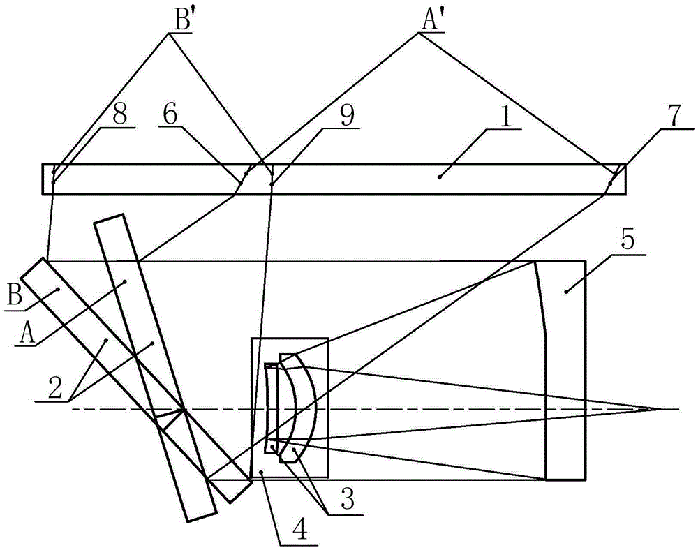
[0018] figure 1 It is a schematic diagram of the optical system of the high-precision miniaturized airborne star sensor of the present invention. In the figure, the optical system is composed of a light window 1 , a swing mirror 2 , a secondary mirror group 3 , a secondary mirror frame 4 , and a primary mirror 5 . Among them, A and B are the two extreme positions of the swing mirror 2 respectively, and the rays 6, 7, 8, and 9 are the two fields of view A' and B corresponding to the swing mirror when the swing mirror swings to the two extreme positions. At the same time, the light beams represented by rays 6 and 7 and the light beams represented by rays 8 and 9 are respectively the edge field beams of the maximum scanning field of view required by the star sensor.

[0019] The light window 1 is made of window glass with high transmittance and is installed on the skin surface of the ca...


PUM


Abstract

The invention, which belongs to the star sensor technology, particularly relates to an optical system for a high-precision miniaturization star sensor in an airborne environment. The optical system is composed of an optical window, an oscillating mirror, a secondary mirror group, a secondary mirror frame, and a primary mirror. The secondary mirror group is fixed in the secondary mirror frame. The secondary mirror group and the primary mirror form a small-view-field convergence imaging system based on a cassegrain two-mirror system; and the optical axis of the optical window is perpendicular to the optical axis of the small-view-field convergence imaging system. The oscillating mirror is arranged on the optical axis of the small-view-field convergence imaging system in an inclined mode and faces the optical window in an inclined mode. According to the invention, the size of the airborne star sensor can be reduced to be the half or less of the size of the existing star sensor in the prior art; the imaging can be guaranteed to be in a diffraction limit state; and requirements of miniaturization and high precision can be met simultaneously. Besides, the optical system has advantages of simple structure, high reliability, low process manufacturing difficulty, and low cost and can adapt to the airborne working environment well; and the system that can be popularized and applied easily has the great practical value.

Description

technical field [0001] The invention belongs to the star sensor technology, in particular to an optical system of a high-precision miniaturized star sensor used in an airborne environment. Background technique [0002] The star sensor is used in combination with the inertial navigation system to locate the carrier. The current mature star sensors are mainly used in the space-borne / bomb-borne and ship-borne fields. The difference from the application in the air-borne field of the present invention is that the working environment of the space-borne / bomb-borne star sensors is located at an altitude of more than 30km. The dark background of star measurement makes it easy to achieve miniaturization on the premise of ensuring the quality of optical imaging; the working environment of the shipborne star sensor is located near the horizontal plane, because the ship does not have high requirements for the size and weight of the equipment, so the large optical structure is used to Gu...

Claims


Application Information

Patent Timeline
Patent Type & Authority Applications(China)
IPC IPC(8): G02B27/00G02B26/08
CPCG02B26/0816G02B27/0031
Inventor 丁小昆魏青胡晓东王维科
Owner FLIGHT AUTOMATIC CONTROL RES INST
Why Eureka
Try Eureka