Cockpit attitude control system, method and device

An attitude control and cockpit technology, applied in general control systems, control/regulation systems, program control, etc., can solve the problems of difficult to meet tourists, simple structure, and high safety requirements, and achieve increased viewing, simple mechanism, and safety. high effect

Active Publication Date: 2019-02-15
华强方特(深圳)智能技术有限公司
View PDF5 Cites 0 Cited by
  • Summary
  • Abstract
  • Description
  • Claims
  • Application Information

AI Technical Summary

Problems solved by technology

[0002] In the design of the traditional manned cockpit mechanism, most of them move in a straight line on a limited track or in a plane. The style is single and the structure is simple. It is difficult to meet the increasing needs of tourists. The corresponding three-dimensional movement is complicated due to the mechanism. High safety requirements and complicated maintenance make the past cases less

Method used


Image

  • Cockpit attitude control system, method and device
  • Cockpit attitude control system, method and device
  • Cockpit attitude control system, method and device

Examples


specific Embodiment approach

[0020] Cockpit attitude control system of the present invention, its preferred embodiment is:

[0021] Including the rotary drive, the boom pitch drive, the small arm pitch drive and the swing drive, the four drives are respectively connected to the control ends of the drive motors of the rotation axis, the boom pitch axis, the small arm pitch axis and the swing axis, and are used to drive the corresponding motor;

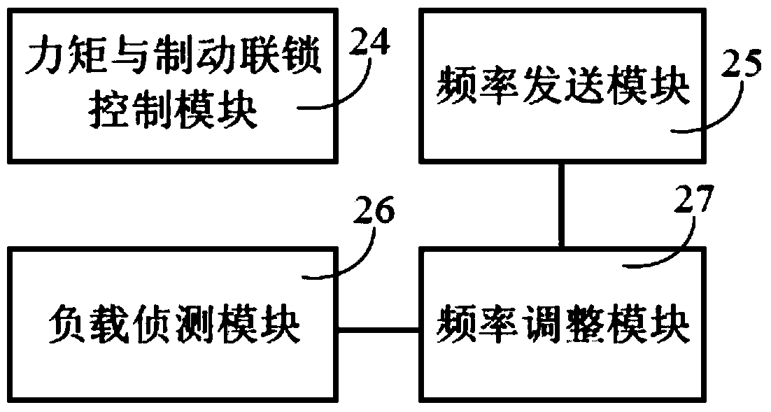
[0022] Each driver is connected to a braking resistor, and the four drivers are respectively connected to the control terminals of the braking device of the corresponding motor, and are used to control the torque of the braking device of the motor and the braking interlock control module according to the output torque of the motor.

[0023] It also includes a controller, which is communicatively connected with the driver and capable of controlling the motor corresponding to the driver and its braking device.

[0024] The speed given control terminal, position give...

specific Embodiment

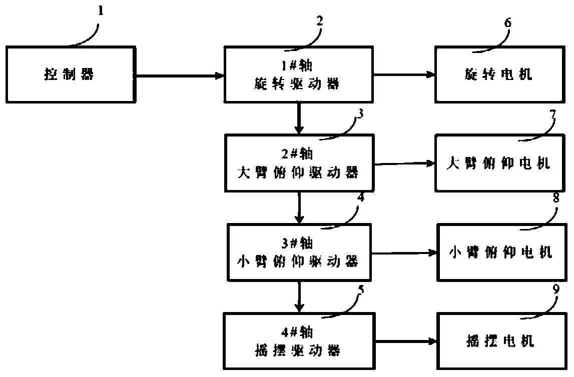
[0040] Such as figure 1 As shown, including: drivers 2-5 and controller 1;

[0041] Wherein, the controller 1 communicates with the drivers 2-5, and can control the drivers 2-5 to drive the main motors 6-9 respectively;

[0042] Controller 1 communicates with drivers 2-5. Specifically, the speed-given command control terminal, position-given control terminal, and control word of controller 1 can be communicated with the speed-given command input terminals, The position reference input terminal is connected with the control word input terminal.

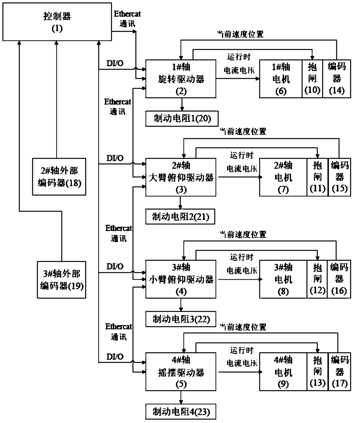
[0043] Such as figure 2 As shown, a braking resistor is set on the basis of the above control system, and each driver is connected to a braking resistor separately. When the motor is in the state of braking or decelerating, the rectified voltage increases, and the energy is consumed on the braking resistor to achieve the effect of stable speed control.

[0044] The above-mentioned control system can also be provided with motors th...


PUM


Abstract

The invention discloses a cabin attitude control system, a method and equipment. A rotation driver, a large arm pitching driver, a small arm pitching driver and a swing driver are included. The four drives are connected to control ends of driving motors of a rotation shaft, a large arm pitching shaft, a small arm pitching shaft and a swing shaft respectively so as to drive the corresponding motors. Each driver is connected to a brake resistor respectively. The four drivers are connected to control ends of brake apparatuses of the corresponding motors respectively so as to control moments of the brake apparatuses of the motors according to output torques of the motors and brake an interlocking control module. A controller is also included. The controller is connected to the drivers in a communication connection mode so as to control the motors corresponding to the drivers and the brake apparatuses. Through the controller, the plurality of drivers are controlled to operate simultaneously and network communication is adopted. Wiring is decreased, the mechanism is simple and safety is high. Stereo motion is realized and simultaneously an ornamental value of a tourist is increased.

Description

technical field [0001] The invention relates to the field of multi-axis control, in particular to a cockpit attitude control system, method and equipment. Background technique [0002] In the design of the traditional manned cockpit mechanism, most of them move in a straight line on a limited track or in a plane. The style is single and the structure is simple. It is difficult to meet the increasing needs of tourists. The corresponding three-dimensional movement is complicated due to the mechanism. High safety requirements and complicated maintenance make the past cases less. Contents of the invention [0003] The object of the present invention is to provide a cockpit attitude control system, method and equipment with high safety, simple mechanism and convenient maintenance. [0004] The purpose of the present invention is achieved through the following technical solutions: [0005] The cockpit attitude control system of the present invention includes a rotary driver, a...

Claims


Application Information

Patent Timeline
Patent Type & Authority Patents(China)
IPC IPC(8): G05B19/048
CPCG05B19/048
Inventor 李明戎志刚刘道强高敬义
Owner 华强方特(深圳)智能技术有限公司
Why Eureka
Try Eureka