Integrated LED light source thermal conductive structure and implementation method therefor

A technology of LED light source and heat conduction structure, which is applied in the direction of semiconductor devices, electrical components, electric solid devices, etc., can solve the problems of poor stability and consistency, achieve the effects of reducing thermal interface, prolonging long-term life, and reducing thermal resistance

Inactive Publication Date: 2016-03-23
FUJIAN CAS CERAMIC OPTOELECTRONICS TECH CO LTD
View PDF11 Cites 3 Cited by
  • Summary
  • Abstract
  • Description
  • Claims
  • Application Information

AI Technical Summary

Problems solved by technology

Moreover, this type of adhesive is generally physically mixed, and its stability and consiste

Method used


Image

  • Integrated LED light source thermal conductive structure and implementation method therefor
  • Integrated LED light source thermal conductive structure and implementation method therefor
  • Integrated LED light source thermal conductive structure and implementation method therefor

Examples


Example Embodiment

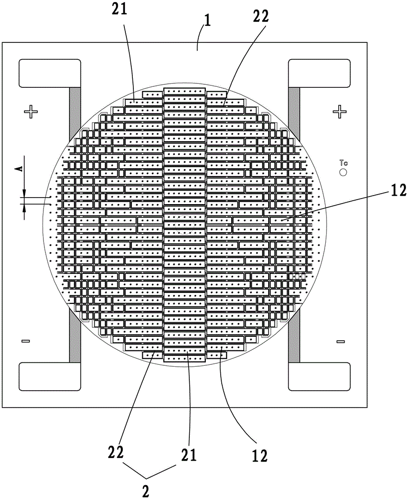
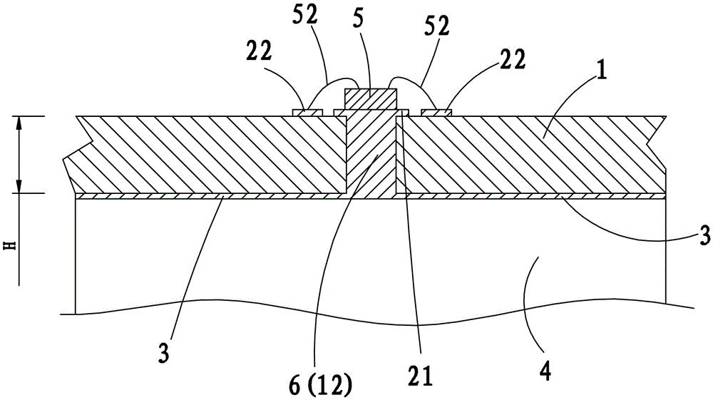
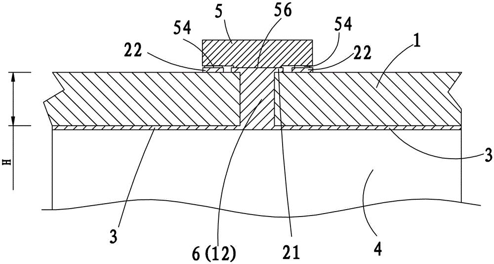
[0031] like Figure 1 to Figure 3 As shown, the heat conduction structure of the integrated LED light source of the present invention includes an insulating substrate 1, a circuit layer 2 and a welding surface 3, the circuit layer 2 is arranged on the front side of the insulating substrate 1, and the welding surface 3 is arranged on the insulating substrate 1 On the opposite side, weld the radiator 4 with metal solder with a thermal conductivity above 60W / m.k.

[0032] The circuit layer 2 is divided into a plurality of die-bonding regions 21 and a plurality of bonding wire regions 22, and there is no electrical connection between the die-bonding regions 21 and the bonding wire regions 22, and the LED chips 5 are welded corresponding to the through holes 12 one by one. An electrical connection is formed on the die-bonding area 21 and the corresponding bonding wire area 22 .

[0033] The insulating substrate 1 is provided with a through hole 12 penetrating through the insulatin...


PUM

PropertyMeasurementUnit
Thermal conductivityaaaaaaaaaa

Abstract

The invention provides an integrated LED light source thermal conductive structure. The integrated LED light source thermal conductive structure comprises an insulating base material, a circuit layer and a welding surface, wherein a through hole, penetrating through the whole piece of the base material, is formed in the insulating base material; a thermal conductive body is embedded in the through hole; an LED chip is welded on the circuit layer through die-bond welding; the heat generated by the LED chip reaches the welding surface through the circuit layer and the thermal conductive body embedded in the through hole; and a substrate and a radiator can be firmly welded together through a reflow soldering manner. The thermal conductivity of metal solder is about more than 60W/m.k that is considerably higher than the thermal conductivity of a common binder of 1.0W/m.k; and the thermal interfaces between the chip and the radiator are reduced and the thermal resistance is greatly reduced, so that the long-term service life of the LED chip can be prolonged.

Description

technical field [0001] The invention relates to an integrated LED light source, in particular to a heat conduction structure of an integrated LED light source and a realization method thereof. Background technique [0002] LED light sources have been widely used in various fields due to their advantages of energy saving, environmental protection, and long life. [0003] Existing LED light sources generally adhere chips to substrates or brackets with an adhesive, which is mostly a mixture of epoxy resin and ceramic or metal powder. The chip is fixed by the adhesive properties of the resin and filled material to conduct heat. Moreover, this type of adhesive is generally physically mixed, and its stability and consistency are poor. As power increases, thermal conductivity and long-term stability are challenged. [0004] Therefore, high-power LED packaging needs to improve and improve the existing technology. Contents of the invention [0005] The technical problem to be s...

Claims


Application Information

Patent Timeline
IPC IPC(8): H01L33/64H01L33/00
CPCH01L33/64H01L33/641H01L33/642H01L33/644H01L33/647H01L2933/0075H01L2224/16225H01L2224/48091H01L33/00H01L2924/00014
Inventor 叶尚辉张杰钦曹永革
Owner FUJIAN CAS CERAMIC OPTOELECTRONICS TECH CO LTD
Why Eureka
Try Eureka