A battery module support frame and battery module

A battery module and support frame technology, which is applied to battery pack components, circuits, electrical components, etc., can solve the problems of complex combination and connection, damage to the battery pack, and troublesome assembly, and achieve a simple assembly process, firm structure, and convenient connection. Effect

Active Publication Date: 2018-09-21
安徽超锂电子科技有限公司
View PDF3 Cites 0 Cited by
  • Summary
  • Abstract
  • Description
  • Claims
  • Application Information

AI Technical Summary

Problems solved by technology

[0002] In the prior art, when multiple batteries are used in combination, especially when multiple single cylindrical batteries are combined in series and parallel to form a large-capacity, high-voltage battery pack, welding (laser welding or resistance welding) is generally used for connection. Such as the published patent: CN103682478B, but the welding method will generate local high temperature and certain mechanical pressure, which may cause damage to the battery and cause battery leakage, etc.
Moreover, the reliability of welding is also poor, and it cannot be completely detected. Maintenance, disassembly, etc. will damage the entire battery pack. The traditional resistance welding method is also poor in vibration resistance, and it is only suitable for the combined connection of batteries in two-dimensional directions. The combined connection in the three-dimensional direction is more complicated and less secure
[0003] Although there are also some battery packs that use a support frame structure to achieve a three-dimensional combination without welding and reduce damage to the battery, such as the patent CN104733673A, but the battery is upright between the upper and lower brackets, and is stuck by the positioning holes of the upper and lower brackets. The positive and negative terminals of the battery are fixed, the impact resistance is poor, and it is not resistant to vibration
Patent CN102110795B, although it is improved, the battery is placed horizontally on the bracket, which solves the problem of poor impact resistance, but there are too many parts in the bracket, the assembly is troublesome, the manufacturing process and manufacturing difficulty are increased, and the cost is high. It is inconvenient to maintain, and it also increases the instability of the connection between the various components

Method used


Image

  • A battery module support frame and battery module
  • A battery module support frame and battery module
  • A battery module support frame and battery module

Examples


Embodiment 1

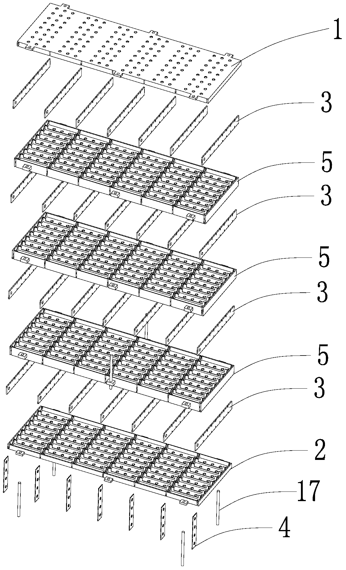
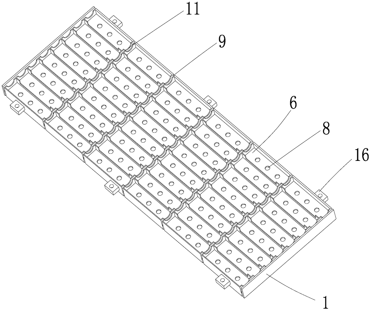
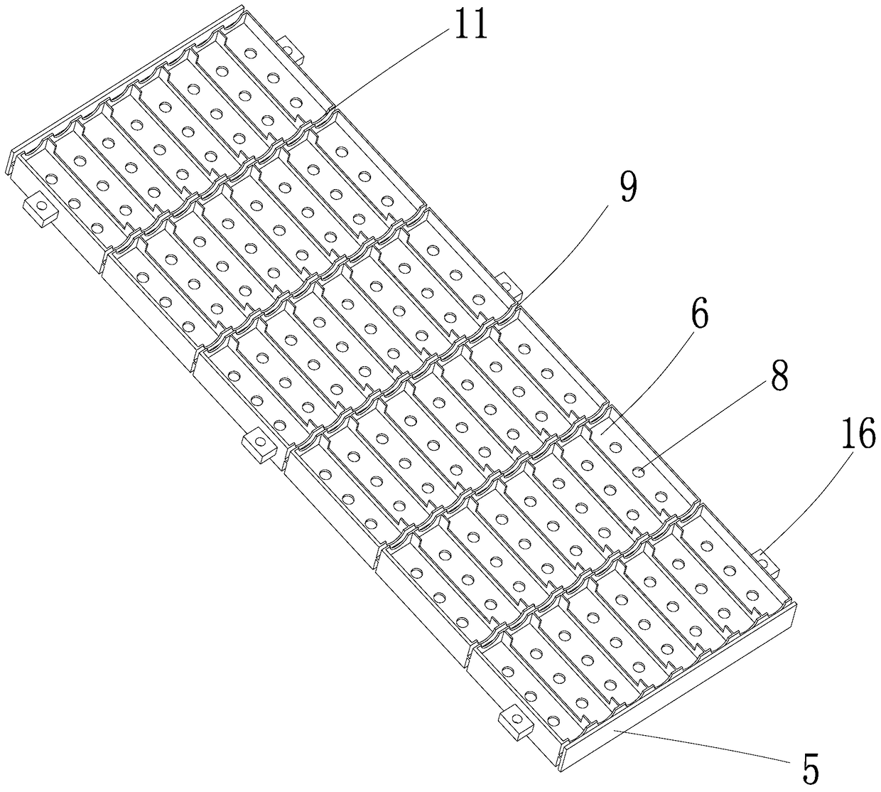
[0032] Such as Figure 1-5 As shown, a battery module support frame includes an insulating upper bracket 1, an insulating lower bracket 2, a first electrical connector 3, a second electrical connector 4 and an insulating intermediate bracket 5. In this embodiment, the intermediate bracket The number of 5 is 3, which are stacked between the upper bracket 1 and the lower bracket 2 in sequence. The upper bracket 1 is provided with several rows of battery storage slots 6, and each row of battery storage slots 6 is provided with several battery storage slots 6 side by side. In this embodiment, the upper support 1 is provided with six rows of battery accommodation grooves 6, and each row of battery accommodation grooves 6 has eight battery accommodation grooves 6. Of course, in other embodiments, the middle bracket 5 and the row of battery accommodation grooves 6 The number and the number of battery accommodating slots 6 in each row can be set according to actual needs. The width o...

Embodiment 2

[0041] The difference between this embodiment and Embodiment 1 is that there is no intermediate support 5 and second electrical connector 4 , that is, there is only one layer of batteries 7 .

[0042] The assembly process of the battery module of this embodiment is as follows:

[0043] First place the lower bracket 2, and then place a first electrical connector 3 in each first electrical connector receiving groove 9 on the lower bracket 2, and make the shrapnel or spring 12 on the first electrical connector 3 face the same direction when placing , the first through holes 14 of the first electrical connector 3 are all facing the same side direction of the bracket; The elastic piece 12 is in contact, and the positive pole is in contact with the side of the first electrical connector 3 without the spring or the elastic piece 12 through the opening 11 of the side wall of the first electrical connector receiving groove 9, so that the battery is installed; The battery accommodating...

Embodiment 3

[0045] Such as Figure 9 As shown, the difference between this embodiment and the first embodiment is that two first electrical connectors 3 are placed in each complete first electrical connector receiving groove, and these two first electrical connectors 3 are placed on the left and right for The parallel connection of the same row of batteries 7 turns the same row of batteries 7 into two parallel parts, and further turns the same layer of batteries into two series-parallel parts, and then connects the two series-parallel parts in series.

[0046] The assembly process of this embodiment is similar to that of Embodiment 1. First, the lower bracket 2 is placed, but a first electrical connector 3 is placed on the left and right in each first electrical connector receiving groove 9 of the lower bracket 2, and when placed, the left Part of the elastic piece or spring 12 on the first electrical connector 3 faces the same direction, the elastic piece or spring 12 on the right part o...


PUM


Abstract

The invention relates to the technical field of batteries. The invention discloses a battery module support frame and a battery module. The battery module support frame includes an insulating upper bracket, a lower bracket and a first electrical connector. The upper bracket is provided with several rows of battery accommodation grooves, and each row The battery storage slots are arranged side by side with several battery storage slots. The end of each row of battery storage slots used to place the positive or negative poles of the battery is called a node, and the nodes of the several rows of battery storage slots are all provided with first electrical connectors. The lower bracket is provided with a battery storage slot corresponding to the upper bracket and a first electrical connector storage slot, and the first electrical connector is arranged in the first electrical connector storage slot for the same row The parallel connection of the batteries in the battery containing grooves and the series connection of the batteries in the battery containing grooves of adjacent rows. The invention has no welding on the battery, simple assembly process, convenient installation and maintenance, good thermal performance and vibration resistance.

Description

technical field [0001] The invention belongs to the technical field of batteries, and in particular relates to a battery module support frame and a battery module. Background technique [0002] In the prior art, when multiple batteries are used in combination, especially when multiple single cylindrical batteries are combined in series and parallel to form a large-capacity, high-voltage battery pack, welding (laser welding or resistance welding) is generally used for connection. Such as the published patent: CN103682478B, but the welding method may cause damage to the battery and cause battery leakage due to local high temperature and certain mechanical pressure. Moreover, the reliability of welding is also poor, and it cannot be completely detected. Maintenance, disassembly, etc. will damage the entire battery pack. The traditional resistance welding method is also poor in vibration resistance, and it is only suitable for the combined connection of batteries in two-dimensio...

Claims


Application Information

Patent Timeline
Patent Type & Authority Patents(China)
IPC IPC(8): H01M2/10H01M50/213H01M50/244H01M50/509
CPCH01M50/20Y02E60/10
Inventor 李相哲
Owner 安徽超锂电子科技有限公司
Why Eureka
Try Eureka