Phase locking method based on FPGA and phase-locked loop adopting same

A phase-locked and component technology, which is applied in the automatic control of power, electrical components, etc., can solve the problem of low detection accuracy of the phase-locked loop

Inactive Publication Date: 2016-03-23
XJ ELECTRIC +2
View PDF5 Cites 6 Cited by
  • Summary
  • Abstract
  • Description
  • Claims
  • Application Information

AI Technical Summary

Problems solved by technology

[0003] The purpose of the present invention is to overcome the deficiencies in the prior art, proposes a phase-locked method based on FPGA, solves the problem that the detection accuracy of the phase-locked loop is low, the present invention also proposes a phase-locked loop based on FPGA

Method used


Image

  • Phase locking method based on FPGA and phase-locked loop adopting same
  • Phase locking method based on FPGA and phase-locked loop adopting same
  • Phase locking method based on FPGA and phase-locked loop adopting same

Examples


Embodiment Construction

[0044] The present invention will be described in further detail below in conjunction with the accompanying drawings and embodiments.

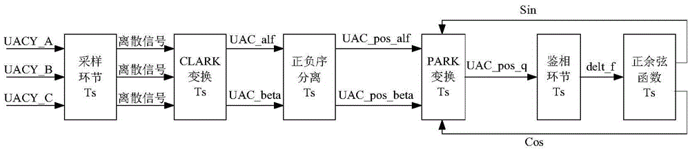
[0045] Based on the FPGA-based phase-locking method, the main process of realizing the method of the present invention in this embodiment is as follows: collecting the grid-side voltage in the system, CLARK transformation, extraction of positive and negative sequence components, PARK transformation and phase identification link, and calculation of voltage phase Measured value; specific steps are as follows:

[0046] Step (1), collecting grid-side voltage in the system:

[0047] Set the program execution step T_step, and sample the grid-side voltage in the flexible DC input system. For each sampling, use the counter to add 1 to T_step, and complete the sampling of the entire program within the program task period Ts to ensure that all function blocks are Execute once in the set order within Ts.

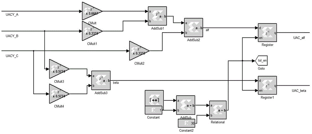
[0048] Step (2), CLARK transformation:

[004...


PUM


Abstract

The invention relates to a phase locking method based on an FPGA (Field Programmable Gate Array) and a phase-locked loop adopting the same. The phase locking method comprises the steps of: collecting a line side voltage in a flexible DC (Direct Current) power transmission system, and converting the acquired voltage into component voltages Uac_alf and Uac_beta of a two-phase static coordinate system; according to the obtained component voltages Uac_alf and Uac_beta, extracting positive and negative sequence components of the component voltages Uac_alf and Uac_beta; and then, carrying out coordinate transformation on the extracted positive sequence components of the component voltages Uac_alf and Uac_beta to obtain a D component and a Q component which correspond to the positive sequence components, outputting the Q component by the phase-locked loop to obtain a frequency error delt_f according to a phase discrimination principle, and obtaining an acquired voltage phase value theta by utilizing the frequency error delt_f so as to calculate sine and cosine results sin theta and cos theta of the theta. According to the invention, a voltage phase of the phase-locked loop is calculated by utilizing the positive sequence components and calculation accuracy of the phase-locked loop is well improved, so that the phase-locked loop has the advantages of high dynamic response speed, small steady state error and the like by the implementing method disclosed by the invention.

Description

technical field [0001] The invention relates to an FPGA-based phase-locked method and a phase-locked loop, and belongs to the field of power electronics and user electric power. Background technique [0002] In the flexible direct current transmission system, the trigger pulse generation of the converter station, the control and protection strategy of the system, etc. all need the reference phase provided by the genlock circuit. Therefore, the genlocked phase link (PhaseLockedLoop, PLL) is an important part of the flexible direct current transmission system. Traditional phase-locked loops generally adopt a phase-locking method based on three-phase synchronously rotating coordinates, which is very effective when the three-phase is balanced. However, under the condition of unbalanced three-phase, the unbalanced input signal will produce double-frequency interference, resulting in a decrease in phase-locking accuracy and affecting the normal operation of the control and protec...

Claims


Application Information

Patent Timeline
Patent Type & Authority Applications(China)
IPC IPC(8): H03L7/085
Inventor 张群郝俊芳王柏恒严兵赵倩陈朋
Owner XJ ELECTRIC
Why Eureka
Try Eureka