Carbon-thermal rail

A technology of carbon hot rail and carbon rod, which is applied in the application field of indoor heating technology, can solve the problems existing in the lower layer, heat up and cool down, uneven temperature distribution, etc., and achieve the effect of energy saving and simple laying

Inactive Publication Date: 2016-03-23
北京中科联众科技股份有限公司
View PDF8 Cites 0 Cited by
  • Summary
  • Abstract
  • Description
  • Claims
  • Application Information

AI Technical Summary

Problems solved by technology

[0002] Traditional geothermal heating mainly heats the room in two ways: conduction and convection. These two heating methods first heat the indoor air, and people in the room get heat from the air. However, the hot air in the room often rises to In the upper layer, the cold air exists in the lower layer, which leads to uneven distribution of indoor temperature, resulting in hot top and cool bottom
Radiators using convection must assist the fan to dissipate heat, but the noise of the fan during operation will affect people's rest

Method used


Image

  • Carbon-thermal rail
  • Carbon-thermal rail
  • Carbon-thermal rail

Examples


Embodiment Construction

[0044] A detailed description will be given below in conjunction with the accompanying drawings.

[0045] Such as Figure 1~3 As shown, it shows a preferred embodiment of the present invention.

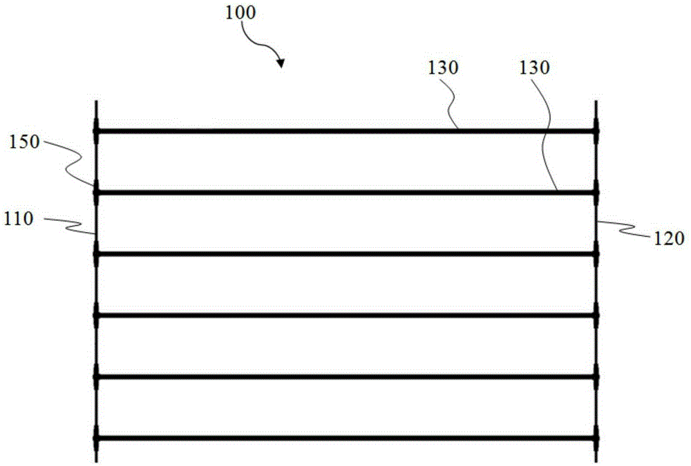
[0046] A carbon thermal rail 100 includes a first power line 110 , a second power line 120 arranged parallel to each other, and a plurality of carbon rods 130 arranged between the first power line 110 and the second power line 120 and parallel to each other. Wherein, the carbon rod 130 and the first power line 110 may be arranged perpendicular to each other, or an included angle may be formed between the carbon rod 130 and the first power line 110 . Preferably, the included angle ranges from 30° to 60°. Wherein, the distance between two adjacent carbon rods 130 is 10-500 mm, preferably 100 mm. Wherein, the carbon rod 130 is an oval strip with a length of 800-1000 mm, preferably 820 mm.

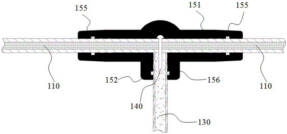
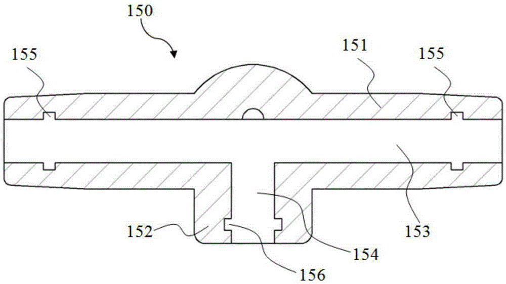
[0047] Two ends of the carbon rod 130 are respectively electrically connected to the first pow...


PUM


Abstract

The invention relates to a carbon-thermal rail, which comprises a first power line, a second power line and a plurality of carbon rods, wherein the first power line and the second power line are arranged in parallel; the plurality of carbon rods are arranged between the first power line and the second power line and are parallel to one another; two ends of each carbon rod are electrically connected with the first power line and the second power line through each conductive anti-drop connecting device respectively; plug protecting devices are arranged at the connected parts of each carbon rod and the first power line and the second power line respectively; each plug protecting device comprises a power line connecting part and a carbon rod connecting part, which are integrally molded in an injection molding manner; a line-through hole which runs through each power line connecting part along the axial direction of each power line connecting part is formed in each power line connecting part; a connecting hole which is communicated with each line-through hole along the axial direction of each carbon rod connecting part is formed in each carbon rod connecting part; first grooves are formed in the walls of the line-through holes along the circumferential direction; and second grooves are formed in the walls of the connecting holes along the circumferential direction.

Description

technical field [0001] The invention relates to the application field of indoor heating technology, in particular to a carbon heating rail. Background technique [0002] Traditional geothermal heating mainly heats the room in two ways: conduction and convection. These two heating methods first heat the indoor air, and people in the room get heat from the air. However, the hot air in the room often rises to In the upper layer, cold air exists in the lower layer, which leads to uneven distribution of indoor temperature, resulting in hot top and cool bottom. The radiators that adopt the convection method all have to assist the fan to dissipate heat, but the noise of the fan during operation will affect people's rest. [0003] In recent years, with the development of the economy and the improvement of income levels, people have higher and higher requirements for the quality of life, and the way of heating has been continuously upgraded. A geothermal device that uses electric en...

Claims


Application Information

Patent Timeline
Patent Type & Authority Applications(China)
IPC IPC(8): H05B3/04F24D13/02
CPCF24D13/024F24D2200/08H05B3/04H05B2203/016H05B2203/026
Inventor 陈滨张雪芳底杏甫王浩
Owner 北京中科联众科技股份有限公司
Why Eureka
Try Eureka