Ultrasonic diagnosis equipment and method for switching ultrasonic probe working state
An ultrasonic probe and ultrasonic diagnosis technology, which is applied in ultrasonic/sonic/infrasonic diagnosis, sonic diagnosis, infrasound diagnosis, etc., can solve the problem of wasting user time and energy, long ineffective working time of ultrasonic probe, increasing ineffective power consumption of ultrasonic probe, etc. problems, to achieve the effect of reducing power consumption and reducing ineffective working time
- Summary
- Abstract
- Description
- Claims
- Application Information
AI Technical Summary
Problems solved by technology
Method used
Image
Examples
Embodiment 1
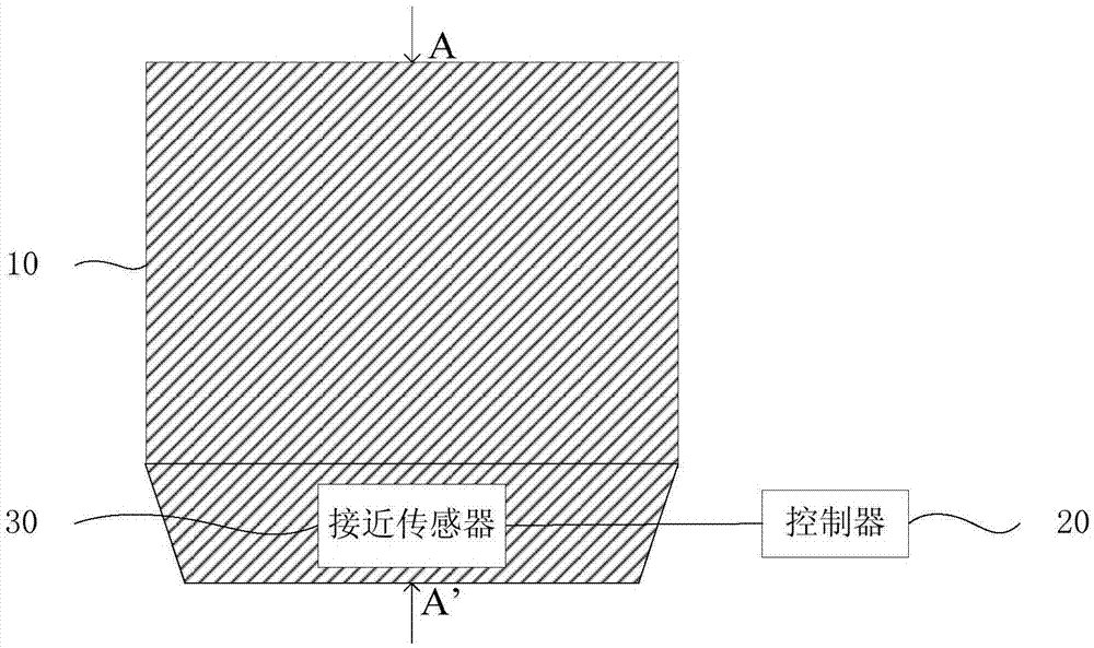
[0023] figure 1 It is a schematic structural diagram of the ultrasonic diagnostic equipment provided by Embodiment 1 of the present invention. This embodiment is applicable to ultrasonic detection in clinical medicine. The ultrasonic probe includes: an ultrasonic probe 10 , a controller 20 and a proximity sensor 30 .
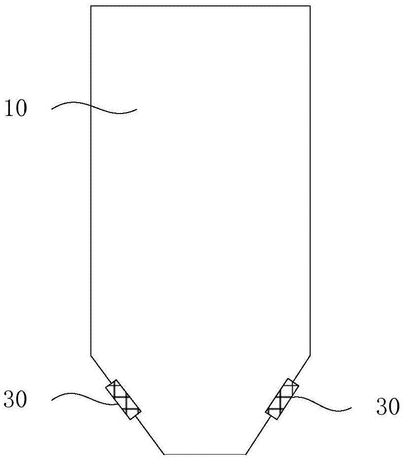
[0024] Wherein, the proximity sensor 30 is arranged at the first set position of the ultrasonic probe 10, and is used for real-time monitoring of the distance parameter between the ultrasonic probe 10 and the target object; the controller 20 is connected with the proximity sensor 30, and is used to The distance parameter obtained at 30 is used to control the working state of the ultrasonic probe 10 . Wherein, the ultrasonic probe 10 includes an acoustic head, and the first set position is near the acoustic head of the ultrasonic probe 10, at a set distance from the acoustic head, such as figure 2 As shown, it is preferably the rear of the sound head, that is, ...
Embodiment 2
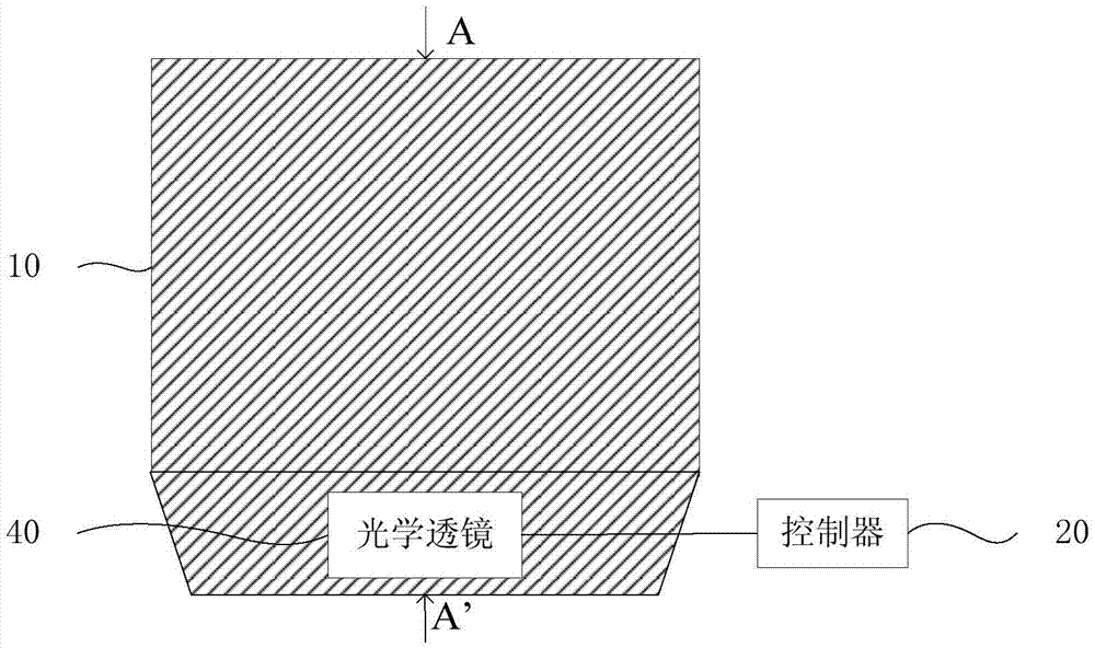
[0034] image 3 It is a schematic structural diagram of the ultrasonic diagnostic equipment provided by Embodiment 2 of the present invention. In this embodiment, an optical lens 40 is added on the basis of the first embodiment, which is used to refract or converge more detection light rays approaching the sensor to the direction of the sound head, and at the same time protect the proximity sensor 30 from interference and wear of the external environment. Such as image 3 and Figure 4 As shown, the ultrasonic probe may further include: an optical lens 40 .
[0035] Wherein, the optical lens 40 is arranged outside the proximity sensor 30 and embedded between the outer shells of the ultrasound probe 10 .
[0036] In order to refract and / or converge the detection light of the proximity sensor 30 to the direction of the sound head, the optical lens 40 can be of any shape and can be arranged at different angles with the proximity sensor 30 . Figure 5 It is a cross-sectional v...
Embodiment 3
[0040] Figure 7 It is a flow chart of the method for switching the working state of the ultrasonic probe in the ultrasonic diagnostic equipment provided by the third embodiment of the present invention. This embodiment can be applied to the ultrasonic diagnostic equipment described in any of the above-mentioned embodiments, and the method includes:
[0041] S110. Using one or more proximity sensors to detect distance parameters between the ultrasonic probe and the target object;
[0042] Wherein, the target object refers to an object within the detection range of the proximity sensor, including a human body; the distance parameter refers to a related parameter obtained from the proximity sensor, indicating the distance information from the target object. The number of the proximity sensor can be one or more, preferably, multiple proximity sensors are used to detect the distance parameter between the ultrasonic probe and the target object.
[0043] S120. Compare one or more d...
PUM
 Abstract
Description
Claims
Application Information
 - R&D
- Intellectual Property
- Life Sciences
- Materials
- Tech Scout
- Unparalleled Data Quality
- Higher Quality Content
- 60% Fewer Hallucinations
Browse by: Latest US Patents, China's latest patents, Technical Efficacy Thesaurus, Application Domain, Technology Topic, Popular Technical Reports.
© 2025 PatSnap. All rights reserved.Legal|Privacy policy|Modern Slavery Act Transparency Statement|Sitemap|About US| Contact US: help@patsnap.com


