Low-temperature evaporation and concentration system

A concentration system and low-temperature evaporation technology, applied in evaporation, evaporator accessories, chemical instruments and methods, etc., can solve the problems of system evaporation efficiency decline, large steam consumption, low energy utilization rate, etc.

Inactive Publication Date: 2016-03-30
TECHNICAL INST OF PHYSICS & CHEMISTRY - CHINESE ACAD OF SCI
View PDF10 Cites 7 Cited by
  • Summary
  • Abstract
  • Description
  • Claims
  • Application Information

AI Technical Summary

Problems solved by technology

Most of the current practice is to use multi-effect evaporation and mechanical vapor recompression. The obvious disadvantages of the former are large steam consumption and low energy utilization rate. The latter recovers secondary steam through the steam compressor, which greatly improves the energy utilization rate. , and is currently the most energy-saving and environmentally friendly evaporation method
However, when the evaporation temperature is low, the efficiency of the compressor will drop significantly, and the evaporation efficiency of the system will also decrease accordingly.
For some materials that need to be evaporated at low temperature, such as heat-sensitive materials, if the evaporation temperature is too high, its properties will change, and the use of mechanical vapor recompression will greatly reduce its evaporation efficiency.
[0003] In the chemical and pharmaceutical fields, there are a large number of heat-sensitive substances and substances with high boiling point temperature rise. For heat-sensitive substances, if the temperature is too high during the evaporation and concentration process, their properties will change; for some high-boiling point For substances with temperature rise, the temperature rise of the boiling point increases with the increase of evaporation temperature. If the evaporation temperature is high, the system will consume a lot of energy.

Method used


Image

  • Low-temperature evaporation and concentration system

Examples


Embodiment Construction

[0020] The specific implementation manners of the present invention will be further described in detail below in conjunction with the accompanying drawings and embodiments. The following examples are used to illustrate the present invention, but are not intended to limit the scope of the present invention.

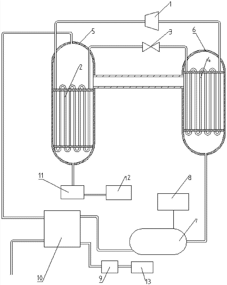
[0021] figure 1 A schematic structural diagram of a low-temperature evaporation and concentration system provided for an embodiment of the present invention, such as figure 1 As shown, the structure of the low-temperature evaporation and concentration system of this embodiment is as follows.

[0022] A low-temperature evaporation and concentration system provided by the present invention includes: an evaporation chamber 5 for placing materials, a condensation chamber 6, a vacuum pump 8, a refrigerant condenser 2, a refrigerant evaporator 4, a throttling device 3 and a compressor 1;

[0023] The refrigerant outlet of the refrigerant evaporator 4 is connected to one end of...


PUM


Abstract

The invention provides a low-temperature evaporation and concentration system and relates to the field of evaporation and concentration. The system comprises an evaporation chamber used for material evaporation, a condensation chamber, a vacuum pump, a refrigerant condenser, a refrigerant evaporator, a throttling device and a compressor, wherein the evaporation chamber is communicated with the condensation chamber, the vacuum pump is connected with the evaporation chamber or the condensation chamber, the refrigerant condenser is arranged in the evaporation chamber, and the refrigerant evaporator is arranged in the condensation chamber; a refrigerant outlet of the refrigerant evaporator is connected with one end of the compressor, a refrigerant inlet of the refrigerant condenser is connected with the other end of the compressor, a refrigerant inlet of the refrigerant evaporator is connected with one end of the throttling device, and a refrigerant outlet of the refrigerant condenser is connected with the other end of the throttling device. According to the system, the discharge temperature of the compressor is adjusted through the throttling device, so that a material can be evaporated and condensed at the lower temperature.

Description

technical field [0001] The invention relates to the field of evaporation concentration, in particular to a low-temperature evaporation concentration system. Background technique [0002] Evaporation and concentration process is widely used in chemical, pharmaceutical, wastewater treatment and other industries, the purpose is to remove the moisture in the material, to achieve the purpose of extracting solid products in the material or reducing the amount of the material. Most of the current methods are multi-effect evaporation and mechanical vapor recompression. The obvious disadvantages of the former are large steam consumption and low energy utilization rate. The latter recovers the secondary steam through the steam compressor, which greatly improves the energy utilization rate. , and is currently the most energy-saving and environmentally friendly evaporation method. But when the evaporating temperature is low, the efficiency of the compressor will drop significantly, and...

Claims


Application Information

Patent Timeline
Patent Type & Authority Applications(China)
IPC IPC(8): B01D1/00B01D1/30
CPCB01D1/0047B01D1/30
Inventor 杨俊玲杨鲁伟张振涛
Owner TECHNICAL INST OF PHYSICS & CHEMISTRY - CHINESE ACAD OF SCI
Why Eureka
Try Eureka