Self-contained nail fixing connectors
A technology with fixed connectors and self-contained energy, applied in the direction of nailing tools, manufacturing tools, etc., can solve the problems of poor sealing of kinetic energy agents, uncompact structure, and low safety, and achieve compact structure, increased ease of use, and Ease of use
- Summary
- Abstract
- Description
- Claims
- Application Information
AI Technical Summary
Problems solved by technology
Method used
Image
Examples
Embodiment 1
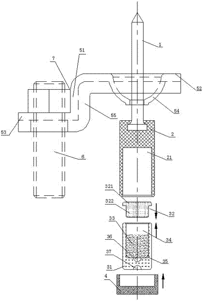
[0023] Such as figure 1 and image 3 As shown, the self-contained nail fixing connector includes the nail body 1, the nail fixing part and the kinetic energy component. In this embodiment, the nail fixing part includes a Z-shaped connector, a connecting nut 6 and a nail bearing housing 2 One end of the nailing bearing housing 2 is provided with a nail cap accommodation chamber, the nail cap of the nailing body 1 is embedded in the nail cap accommodation chamber, and the other end is provided with a kinetic energy assembly installation chamber A 21 that cooperates with the kinetic energy assembly, and the nail loading The tail of the casing 2 has a safety back cover 4 that seals the kinetic energy assembly. Wherein, the Z-shaped connector includes a middle part 51, a first bending head 52 and a second bending head 53, the first bending head 52 is arranged vertically to the upper end of the middle part 51, and the second bending head 53 is perpendicular to the lower end of the ...
Embodiment 2
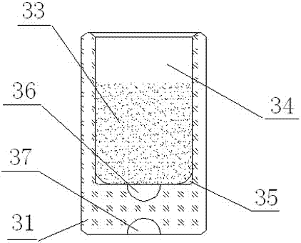
[0028] Such as figure 2 and image 3 As shown, the self-contained nail fixing connector includes the nail body 1, the nail fixing part and the kinetic energy component. In this embodiment, the nail fixing part includes an M-shaped nut 8 and a screw rod 9, and the M-shaped nut is provided with a belt The threaded cavity 81, the nail cap of the nail body 1 is embedded in the cavity 81, the nail body passes through the closed end of the M-shaped nut 8, and one end of the screw 9 is closely matched with the cavity 81 in the M-shaped nut 8, The other end of the screw 9 is provided with a kinetic energy assembly installation cavity B91 for matching with the kinetic energy assembly, and the tail of the screw 9 has a safety back cover 4 for sealing the kinetic energy assembly. The kinetic energy assembly includes a kinetic energy mother shell 31 with an inner cavity 34, a T-shaped sealing cover 32, and a kinetic energy agent 33. A primer 36 is placed at the bottom of the kinetic ene...
Embodiment 3
[0033] Such as Figure 4 and Figure 6 As shown, in the above-mentioned embodiments, the use of solid primer powder has the disadvantages of complicated process, high requirements, high risk in the production process, and loud explosion sound during use, but when using dry powder primer powder as the primer, the explosion speed is fast and the explosion noise is small , so on the basis of Embodiment 1, the kinetic energy housing (kinetic energy mother housing 31) in the kinetic energy assembly is changed as follows to obtain an improved self-energy nailing and fixing connector: the kinetic energy housing includes a first cavity The inner shell 39 of 391 and the outer shell 38 with the second cavity 381, the middle of the first cavity 391 bottom of the inner shell 39 is provided with a detonation port 392, the bottom of the second cavity 381 of the outer shell 38 is for placing primer 36 (preferably dry powder foundation gunpowder), the tail of the shell 38 is provided with a ...
PUM
 Abstract
Description
Claims
Application Information
 - R&D
- Intellectual Property
- Life Sciences
- Materials
- Tech Scout
- Unparalleled Data Quality
- Higher Quality Content
- 60% Fewer Hallucinations
Browse by: Latest US Patents, China's latest patents, Technical Efficacy Thesaurus, Application Domain, Technology Topic, Popular Technical Reports.
© 2025 PatSnap. All rights reserved.Legal|Privacy policy|Modern Slavery Act Transparency Statement|Sitemap|About US| Contact US: help@patsnap.com


