

Wood lathe center
A woodworking lathe and cutting-edge technology, applied in the field of mechanical parts, can solve problems such as easy slipping and affecting work, and achieve the effect of not easily falling off and slipping off
- Summary
- Abstract
- Description
- Claims
- Application Information
AI Technical Summary
Problems solved by technology
Method used
Image

Examples
Embodiment Construction
[0008] The present invention will be further described below in conjunction with the accompanying drawings.
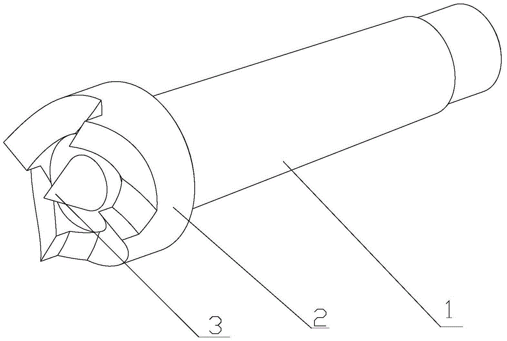
[0009] Such as figure 1 Shown, a kind of top that is used for woodworking lathe, comprises top shank 1 and the top that links to each other with top shank 1, and described top includes fixed ring 3 and the fixed tip 3 that is located at the center of fixed ring, and described fixed ring 2. The edges are wavy and serrated, and the tail end of the top handle 1 is threaded. The workpiece can be completely fixed by the fixing ring, and it is not easy to fall off and slip.
[0010] The above is only a preferred embodiment of the present invention, it should be pointed out that for those of ordinary skill in the art, without departing from the principle of the present invention, some improvements and modifications can also be made, and these improvements and modifications are also possible. It should be regarded as the protection scope of the present invention.
PUM
 Abstract
Description
Claims
Application Information