
3D printer wire feeding structure

A technology of 3D printer and wire feeding structure, applied in the direction of additive processing, etc., can solve the problems of difficulty, complex wire feeding structure, inconvenient spacing adjustment, etc., to avoid slippage, compact structure, and simple structure.

Inactive Publication Date: 2016-03-30
UNIV OF JINAN
View PDF4 Cites 6 Cited by
  • Summary
  • Abstract
  • Description
  • Claims
  • Application Information

AI Technical Summary

Problems solved by technology

[0002] In the wire feeding structure of the 3D printer in the prior art, the power is transmitted to the wire feeding driving wheel through the wire feeding motor, and the printing wire made of plastic and other materials is conveyed by the extrusion and friction between the driving wheel, the driven wheel and the printing wire. After the printing head is heated and melted, it is ejected from the nozzle to form the designed shape. The wire feeding structure of the existing printer is relatively complicated, and the distance between the driving wheel and the driven wheel is inconvenient to adjust. In addition, the head of the new printing wire It is not easy to lead into the printing wire channel at the lower part of the wire feeding structure without being guided

Method used


Image

  • 3D printer wire feeding structure
  • 3D printer wire feeding structure
  • 3D printer wire feeding structure

Examples


Embodiment Construction

[0016] In order to better understand the present invention, the implementation manner of the present invention will be explained in detail below in conjunction with the accompanying drawings.

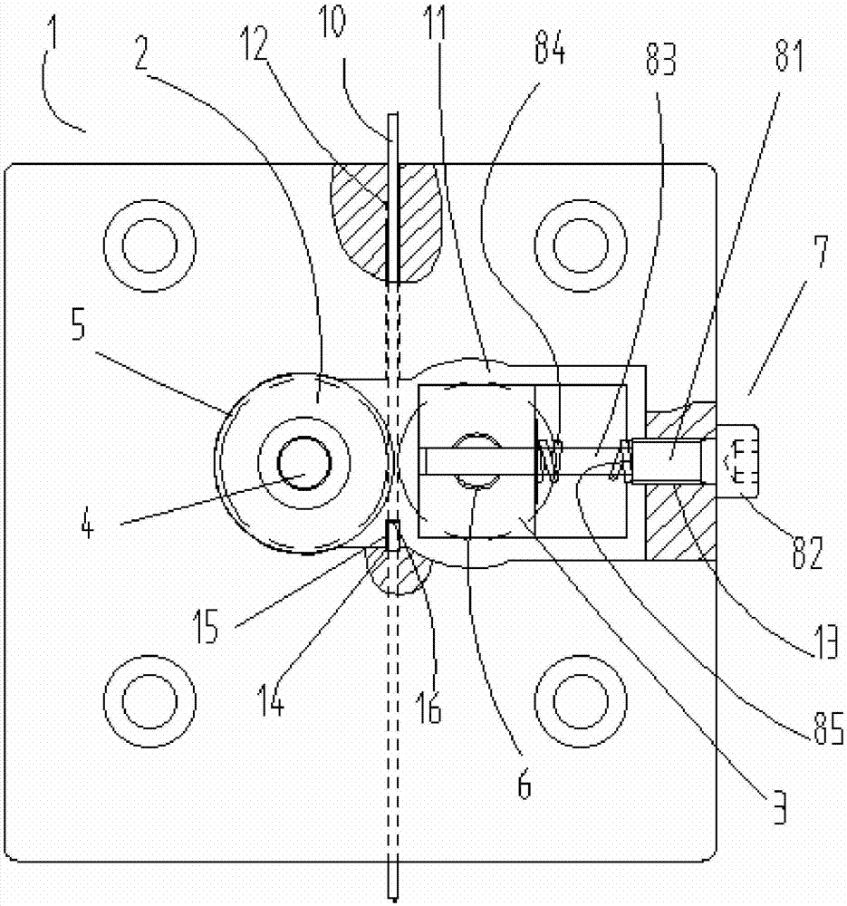
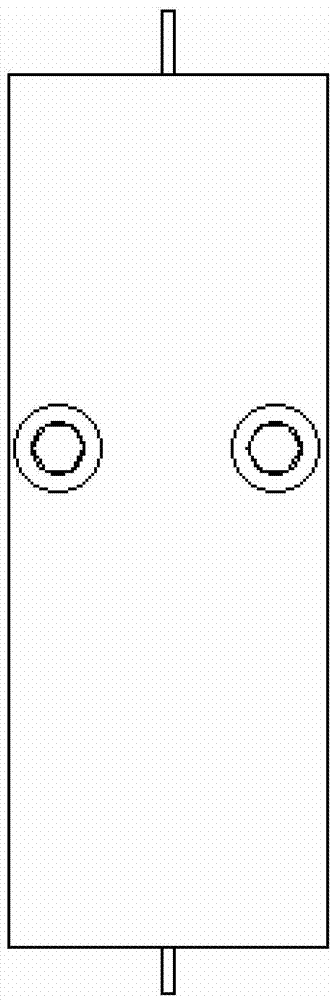
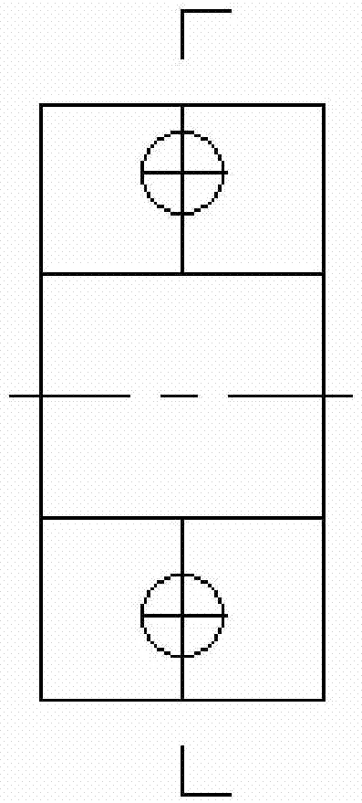
[0017] Such as Figure 1 to Figure 4 As shown, a wire feeding structure of a 3D printer includes a fixed base 1, the fixed base 1 is connected to a wire feeding motor, a cavity 11 is provided in the middle of the fixed base 1, and a wire feeding device is provided on one side of the cavity. The driving wheel 2 and the other side are provided with a driven wheel 3 structure, the driving wheel 2 is connected with the driving wheel shaft 4, the driving wheel shaft 4 is supported on the inner wall of the cavity of the fixed seat through the bearing 5, and the driven wheel 3 is connected with the driven wheel shaft 6 connection, a vertical printing filament channel 12 is provided on the fixed seat 1, the driven wheel shaft 6 is connected to the horizontal position adjustment structure 7 of t...


PUM


Abstract

The invention discloses a 3D printer wire feeding structure. The 3D printer wire feeding structure comprises a fixed base; the fixed base is connected with a wire feeding motor; a cavity is formed in middle of the fixed base; a wire feeding driving wheel is arranged on one side in the cavity, and a driven wheel structure is arranged on the other side in the cavity; the driving wheel is connected with a driving wheel shaft; the driving wheel shaft is supported on the inner wall of the cavity of the fixed base through a bearing; the driven wheel is connected with a driven wheel shaft; a printing wire channel is formed in the fixed base in the perpendicular direction; the driven wheel shaft is connected with a driven wheel shaft horizontal position adjusting structure; and the driving wheel is matched with the driven wheel to convey printing wires to a printing head part. The 3D printer wire feeding structure is simple and compact in structure, is convenient for disassembly, replacement and maintenance, can conveniently and precisely adjust a shaft distance between the driving wheel and the driven wheel through the horizontal position adjusting structure, and can reliably convey the printing wire materials to a melting position of the printing head part for timely melting to satisfy the printing requirements.

Description

technical field [0001] The invention relates to the technical field of printers, in particular to a wire feeding structure for a 3D printer. Background technique [0002] In the wire feeding structure of the 3D printer in the prior art, the power is transmitted to the wire feeding driving wheel through the wire feeding motor, and the printing wire made of plastic and other materials is conveyed by the extrusion and friction between the driving wheel, the driven wheel and the printing wire. After the print head is heated and melted, it is sprayed out from the nozzle to form the designed shape. The wire feeding structure of the prior art printer is relatively complicated, and the distance between the driving wheel and the driven wheel is inconvenient to adjust. In addition, the head of the new printing wire It is not easy to lead into the printing wire channel at the lower part of the wire feeding structure without being guided. Contents of the invention [0003] The purpos...

Claims


Application Information

Patent Timeline
Patent Type & Authority Applications(China)
IPC IPC(8): B29C67/00B29C31/08B33Y30/00
CPCB29C31/08
Inventor 隗德民
Owner UNIV OF JINAN
Learn More