
A contact measuring device and method for the rotary position of a crane

A contact measurement and crane technology, applied in measurement devices, optical devices, transportation and packaging, etc., can solve the problems of electronic compass output deviation, difficult to implement, and strict installation position requirements, so as to avoid being easily affected by environmental electromagnetic fields, The effect of convenient installation and debugging, convenient debugging

Active Publication Date: 2017-03-29
宜昌凯诺电气股份有限公司
View PDF5 Cites 0 Cited by
  • Summary
  • Abstract
  • Description
  • Claims
  • Application Information

AI Technical Summary

Problems solved by technology

Its use method is relatively simple, but because it is sensitive to the magnetic field, it is applied to the crane. Since the main material of the crane is steel, and there are electromagnetic loads, wires and cables and other substances, the magnetic field distribution is often in a state of change during use, thus As a result, the output of the electronic compass deviates greatly, and the compass needs to be calibrated in time, which is inconvenient to use
For some applications that rely on its measurement results for specific processing, it often seriously affects the reliable realization of its function
The common way of using encoders needs to be connected with the rotating mechanism of the crane, and the installation position is demanding; often lack of installation conditions, it is difficult to implement

Method used


Image

  • A contact measuring device and method for the rotary position of a crane
  • A contact measuring device and method for the rotary position of a crane
  • A contact measuring device and method for the rotary position of a crane

Examples


Embodiment Construction

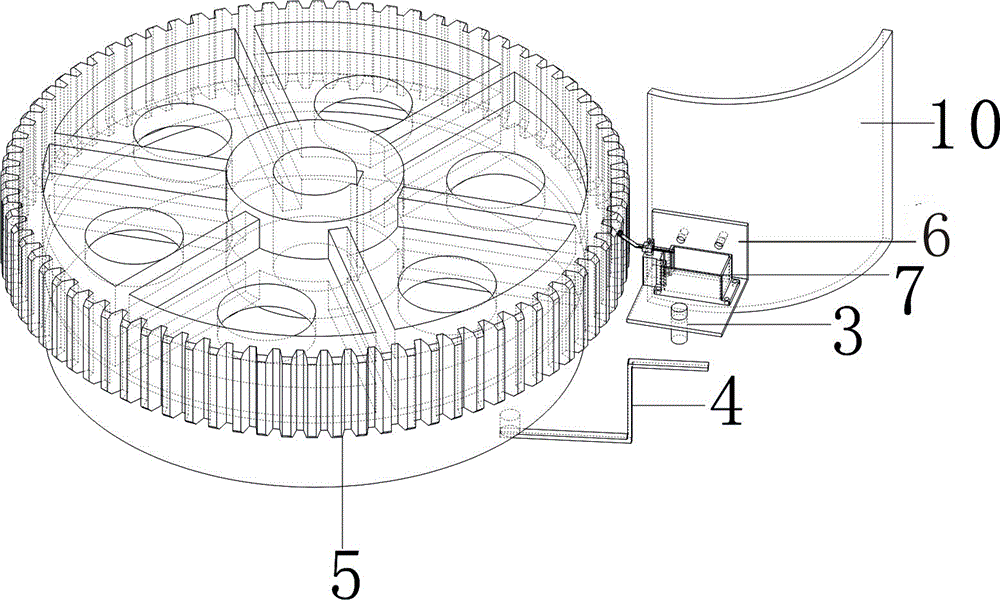
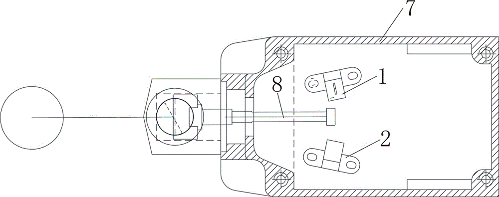
[0017] like figure 1 As shown, a contact measuring device for the slewing position of a crane includes a first gear sensor 1, a second gear sensor 2, a positioning sensor 3 installed on the slewing platform of the crane, and a fixedly installed reflective block 4 and a mechanical limit switch. 7. The first gear sensor 1 and the second gear sensor 2 are located on the left and right sides of the swing rod 8 of the mechanical travel switch 7;

[0018] The first gear sensor 1, the second gear sensor 2, and the positioning sensor 3 are all connected to a signal acquisition / processing module, and the signal acquisition / processing module is connected to a single-chip microcomputer, and the single-chip processing module adopts ATmage8 series 8-bit single-chip microcomputer, and the single-chip microcomputer passes the RS-485 communication module Connect the torque limiter. The first gear sensor 1 and the second gear sensor 2 are infrared through-beam photoelectric sensors; the posi...


PUM


Abstract

A crane slewing position contact-type measurement device and method are disclosed, the crane slewing position contact-type measurement device comprises a first gear sensor, a second gear sensor, a positioning sensor, a reflective piece and a mechanical travel switch, the first gear sensor, the second gear sensor and the positioning sensor are mounted on a crane slewing platform, and the reflective piece and the mechanical travel switch are fixed installed. The first gear sensor and the second gear sensor are respectively located the left side and the right side of an oscillating bar of the mechanical travel switch. The first gear sensor, the second gear sensor and the positioning sensor all are connected with a signal acquisition / processing module, the signal acquisition / processing module is connected with a microcontroller processing module, the microcontroller processing module is connected to a torque limiter via a RS-485 communication module, the first gear sensor and the second gear sensor are infrared correlation-type photoelectric sensors, and the positioning sensor is a reflective photoelectric switch. The crane slewing position contact-type measurement device uses the mechanical travel switch for mechanical-contact-manner detection of concave and convex state of a gear of a large gear ring, crane slewing angle measurement can be realized, and the crane slewing position contact-type measurement device has the easy installation and debugging advantage.

Description

technical field [0001] The invention relates to a contact measuring device and method for the rotary position of a crane, which is used for measuring the rotary angle of a crane platform. Background technique [0002] In the field of measuring the slewing angle of a crane in the prior art, it is common to use an electronic compass. Its use method is relatively simple, but because it is sensitive to the magnetic field, it is applied to the crane. Since the main material of the crane is steel, and there are electromagnetic loads, wires and cables and other substances, the magnetic field distribution is often in a state of change during use, thus As a result, the output of the electronic compass deviates greatly, and the compass needs to be calibrated in time, which is inconvenient to use. For some applications that rely on its measurement results for specific processing, it often seriously affects the reliable realization of its functions. However, the common way of using an...

Claims


Application Information

Patent Timeline
Patent Type & Authority Patents(China)
IPC IPC(8): B66C13/16G01B11/26G01B21/22
Inventor 闫巍周解
Owner 宜昌凯诺电气股份有限公司
Learn More