Offshore drilling shore-based supporting mud plant system

An offshore drilling and mud station technology, applied in the field of offshore drilling, can solve the problems of long time required for station construction, inability to move, limited space on the drilling platform, etc., to simplify equipment operation and maintenance, improve reliability and stability, save money The effect of maintenance time

Active Publication Date: 2016-03-30
HEFEI GENERAL MACHINERY RES INST
View PDF6 Cites 7 Cited by
  • Summary
  • Abstract
  • Description
  • Claims
  • Application Information

AI Technical Summary

Problems solved by technology

[0011] Offshore drilling mainly uses drilling platforms or drilling ships for drilling operations. The construction and operation costs of these offshore equipment are very expensive. At the same time, because the drilling operation itself requires a large number of electromechanical supporting equipment, the space on the drilling platform is very limited, and the configuration of drilling fluid is very limited. It is very time-consuming and labor-intensive. It is a common practice at home and abroad to build shore-based support mud stations and provide drilling fluid-related technical support for offshore drilling.
[0012] In the past, some domestic companies have also built some mud stations, but the traditional fixed storage tanks and fixed equipment are generally used to build stations, which cannot be moved, have single functions, and cannot be expanded. A lot of on-site installation work is required, and the station construction takes a long time. The overall level of automation is low, the degree of integration of complete sets of equipment is low, and the reliability is poor. All the above deficiencies need to be improved urgently

Method used


Image

  • Offshore drilling shore-based supporting mud plant system
  • Offshore drilling shore-based supporting mud plant system
  • Offshore drilling shore-based supporting mud plant system

Examples


Embodiment Construction

[0048] Below in conjunction with accompanying drawing, the implementation process of the present invention will be further described:

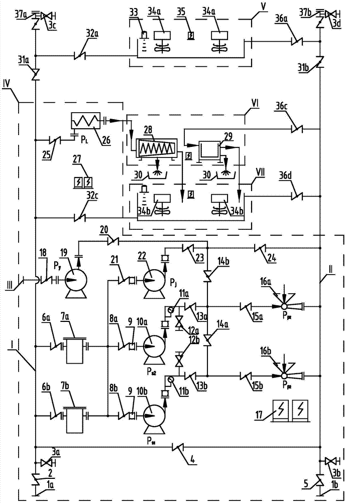
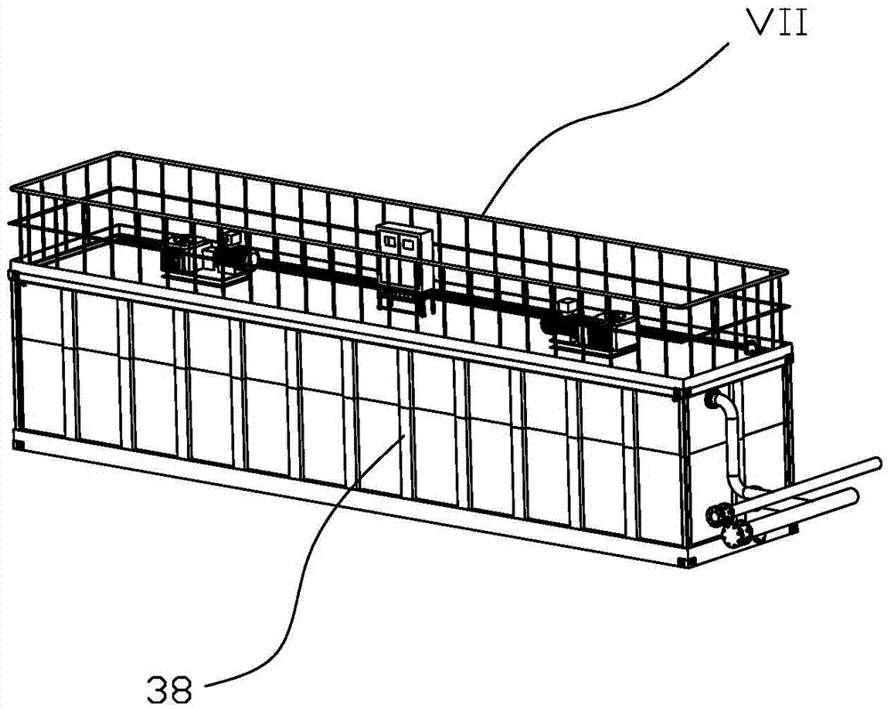
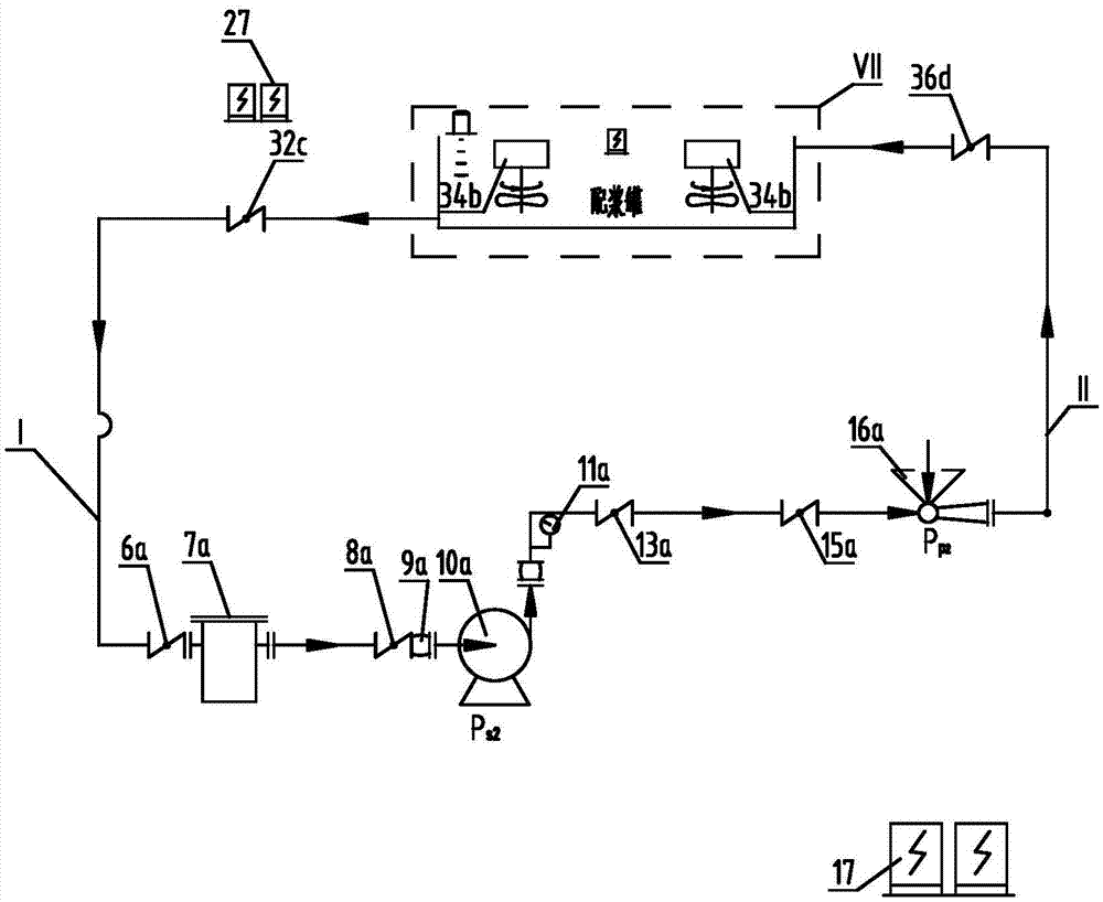
[0049] This embodiment consists of mobile pump skid integrated unit IV, mobile slurry tank integrated unit VII, mobile storage tank integrated unit V, waste liquid treatment skid integrated unit VI, Ⅰ-main liquid inlet pipeline, Ⅱ-main liquid outlet pipeline, Ⅲ-White oil unloading pipeline and corresponding control system.

[0050] Such as figure 1 As shown, the mobile pump skid integration unit IV mainly integrates the first sand pump 10a, the second sand pump 10b, the first mixing funnel 15a, the second mixing funnel 15b, the shear pump 22, the white oil pump 19, the screw pump 26, etc. Fluid conveying equipment can convey different media according to different process requirements such as slurry mixing, storage, and transfer, among which the first sand pump 10a and the second sand pump 10b are mainly used to establish fluid circulation wit...


PUM


Abstract

The invention belongs to the field of offshore drilling and particularly relates to an offshore drilling shore-based supporting mud plant system. The offshore drilling shore-based supporting mud plant system comprises a mobile pump skid integrated unit, a movable slurry preparing tank integrated unit, a movable storage tank integrated unit, a waste liquid treatment skid integrated unit and pipes, a control system and the like for connecting the integrated units. The whole system achieves drilling fluid preparation, transfer and recovery treatment functions and the like, the main constituent devices in the system are all designed to be modular, can be quickly transferred and quickly assembled to build a plant, the mobile pump skid integrated unit, the movable slurry preparing tank integrated unit, the movable storage tank integrated unit and the waste liquid treatment skid integrated unit are all designed to be in forms of stackable standard containers, and the capacity of the mud plant can be increased or decreased under the situation that occupied area is not increased. In addition, interfaces are further reserved for the system, and other functional modules can be added on the basis, such as other functional modules for achieving automatic cement delivery, harmless treatment of waste mud and the like.

Description

technical field [0001] The invention belongs to the field of ocean drilling, and in particular relates to a shore-based supporting mud station system for ocean drilling. Background technique [0002] Drilling fluid is called the blood of oilfield drilling, and its main functions in drilling operations are as follows: [0003] 1), cleaning the bottom of the well, carrying and suspending cuttings; [0004] 2), protect the well wall; [0005] 3), cooling and lubricating drill bit and drill string; [0006] 4), balance formation pressure; [0007] 5), assist in breaking rocks; [0008] 6) Protect oil and gas layers. [0009] The composition of the drilling fluid is very complex, and often needs to be selected according to different geological conditions and drilling techniques, combined with past experience, and it is even possible to replace the drilling fluid with different parameters in different drilling stages of the same well. [0010] In recent years, with the advan...

Claims


Application Information

Patent Timeline
Patent Type & Authority Applications(China)
IPC IPC(8): E21B21/00E21B21/06
CPCE21B21/001E21B21/06
Inventor 周波黄磊秦宗川张继伟廉晓龙胡佳宁张治川孙楠张卓李申燕
Owner HEFEI GENERAL MACHINERY RES INST
Why Eureka
Try Eureka