
Unit control system and control method for energy recovery of pta device

An energy recovery and unit control technology, applied in steam engine installations, mechanical equipment, machines/engines, etc., can solve the problems such as the inability to guarantee the maximum efficiency of the unit, the complex control of the PTA control system, and the long response time of the control system. Utilize, reduce maintenance personnel, control smooth effect

Active Publication Date: 2017-05-24
SHENYANG BLOWER WORKS GRP AUTOMATIC CONTROL SYST ENG
View PDF6 Cites 0 Cited by
  • Summary
  • Abstract
  • Description
  • Claims
  • Application Information

AI Technical Summary

Problems solved by technology

The by-product steam generated by the oxidation reaction heat is recovered by the steam turbine. The existing control system cannot guarantee the maximum efficiency of the unit. When the unit is in normal operation, all the anti-surge valves of the control system are closed. In case of process fluctuations, etc., the anti-surge The vibration valve will open quickly
No, the anti-surge valve cannot be closed all the time, resulting in a part of energy loss
In addition, the control of the PTA control system is complex, requiring a large number of personnel to operate when driving, and the start-up time is long, and the response time of the control system is long, requiring a high configuration of the control system.

Method used

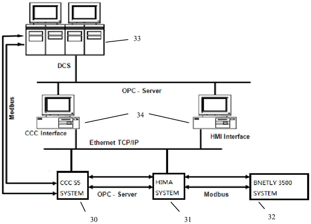
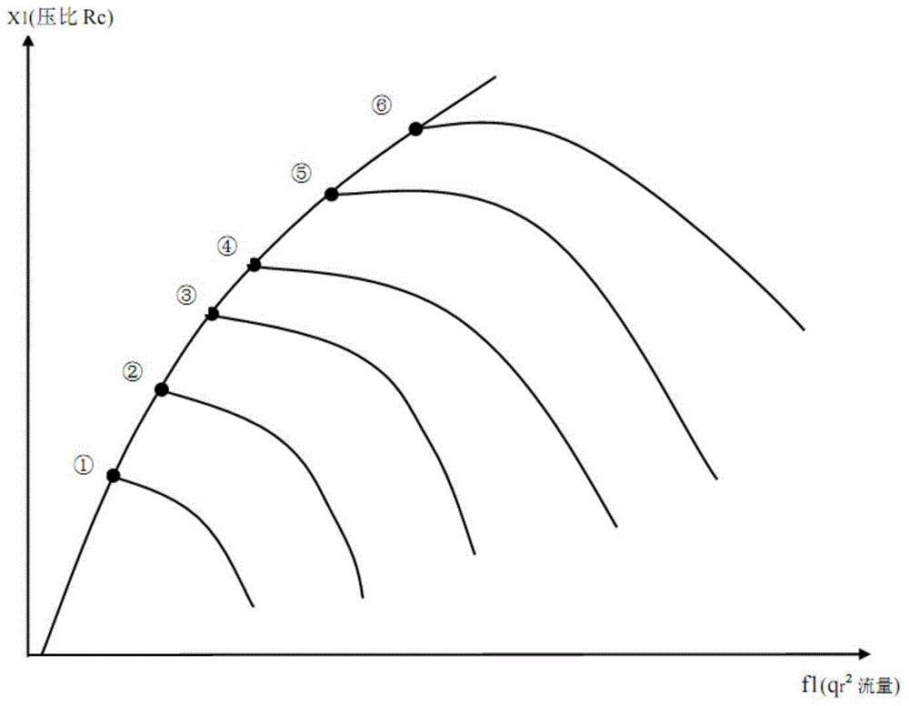

Image

  • Unit control system and control method for energy recovery of pta device
  • Unit control system and control method for energy recovery of pta device
  • Unit control system and control method for energy recovery of pta device

Examples


Embodiment Construction

[0064] The present invention will be further described in detail below in conjunction with the accompanying drawings and embodiments.

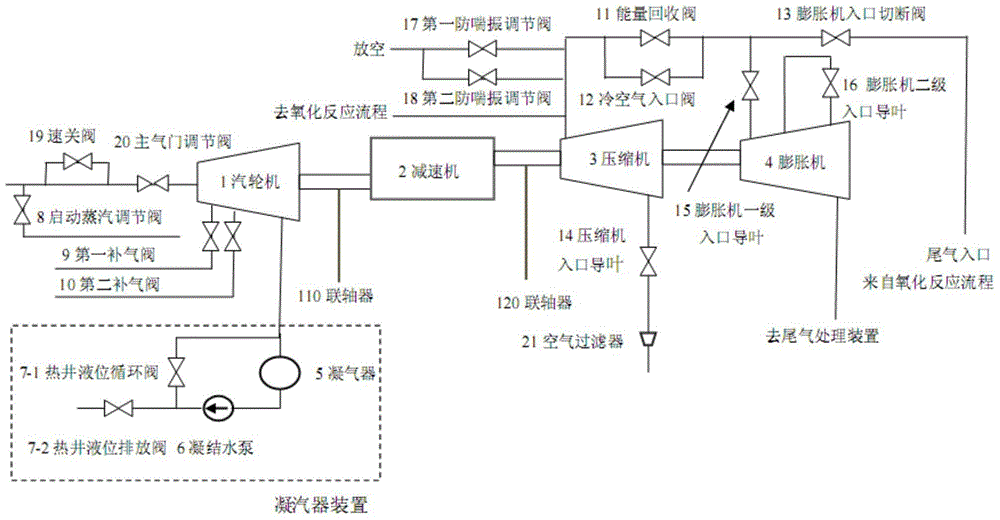
[0065] Such as figure 1 As shown, the present invention includes a steam turbine 1, a reducer 2, a compressor 3, an expander 4 and an auxiliary system to form a compressor unit; wherein, the steam turbine 1 is connected to the reducer 2 through a first coupling 110 to form a drive source unit; The reducer 2 forms a steam turbine-driven compressor unit through the second coupling 120 and the compressor 3; the compressor 3 forms an expander-driven compressor unit through the second coupling 120 and the expander 4; the steam turbine and the expander are formed through two If they are connected by a coupling, the two share the auxiliary system to complete the steam power balance of the device.

[0066] The auxiliary system includes a condenser 5, a condensate pump 6, a hot well liquid level regulating valve (hot well liquid level circulation valv...


PUM


Abstract

The invention relates to a unit control system for energy recovery of a PTA device, in which a steam turbine, a reducer, a compressor, and an expander are sequentially connected, the first auxiliary system is connected with the steam turbine, and the second auxiliary system is connected with the compressor and the expander ; The control device is connected with the steam turbine, the compressor, the first auxiliary system and the second auxiliary system. The control method includes: controlling each valve in the first auxiliary system and the second auxiliary system to be in the initial state; starting the steam turbine to drive the compressor unit to perform the first warm-up; , to warm up the machine for the second time; when the speed reaches the second set value and maintains the set time, it will exceed the critical speed value, and then reach the rated speed; enter the rated speed stage to perform anti-surge control, and control each part of the second auxiliary system The opening and closing of the valve drives the steam turbine to maintain the set speed. The invention realizes the optimal load adjustment and switching, realizes the cascade utilization of energy, and realizes the capacity balance of the whole system.

Description

technical field [0001] The invention relates to an energy recovery control system and method for a PTA device in the chemical industry, specifically a computer control system applied to the control of three sets of PTA devices to ensure the control system and method for the entire energy recovery. Background technique [0002] PTA (Purified Terephthalic Acid) is the abbreviation of purified terephthalic acid. Appearance is white crystal or powder at normal temperature, non-toxic, tasteless, mainly used in the production of polyester (PET), polyester fibers can be obtained by spinning polyester fibers accounting for 70% of chemical synthetic fibers, PTA is the main raw material for the production of polyester fibers , Widely used in chemical fiber, light industry, electronics, construction and other fields. Not only are polyester materials used more and more in food packaging, but also in non-food packaging such as medicine and cosmetics, as well as in industries such as PBT...

Claims


Application Information

Patent Timeline
Patent Type & Authority Patents(China)
IPC IPC(8): F01K23/10
Inventor 宋颖梅李晨
Owner SHENYANG BLOWER WORKS GRP AUTOMATIC CONTROL SYST ENG
Learn More