Fan control system

A fan control and fan technology, applied in the electronic field, can solve the problem of specific parameter settings that cannot rotate the fan, and achieve the effect of simple circuit design

Inactive Publication Date: 2016-03-30
LENOVO (BEIJING) LTD
View PDF6 Cites 4 Cited by
  • Summary
  • Abstract
  • Description
  • Claims
  • Application Information

AI Technical Summary

Problems solved by technology

[0005] The embodiment of the present invention provides a fan control system, which is used to solve the technical problem that the electronic equipment in the prior art cannot set the specific parameters of the fan rotation, and realizes the technical effect of accurately controlling the fan rotation

Method used


Image

  • Fan control system
  • Fan control system
  • Fan control system

Examples


Embodiment Construction

[0033] Embodiment 1 of the present application provides a fan control system, which is used to solve the technical problem that the electronic equipment in the prior art cannot set the specific parameters of the fan rotation, and realizes the technical effect of accurately controlling the fan rotation.

[0034] The technical solution in the embodiment of the present application is to solve the above-mentioned technical problems, and the general idea is as follows:

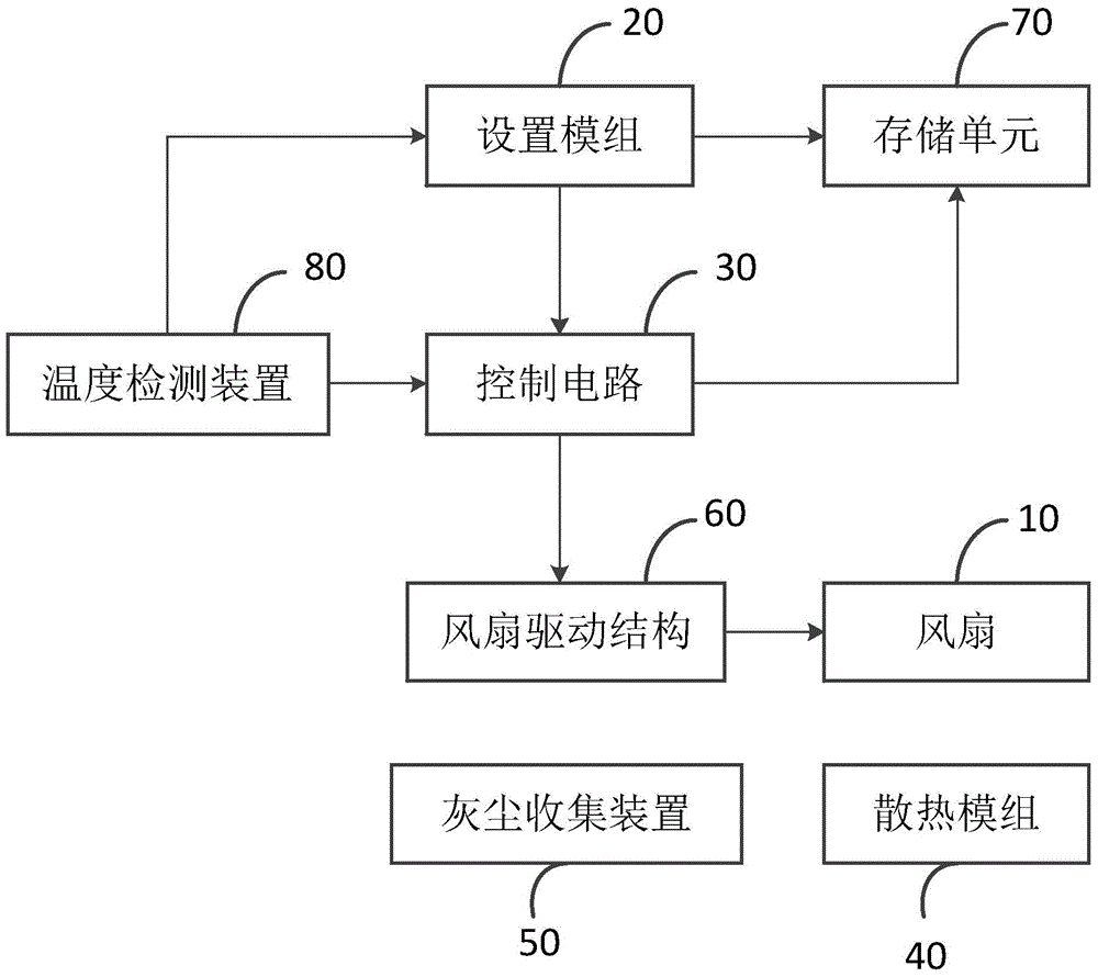
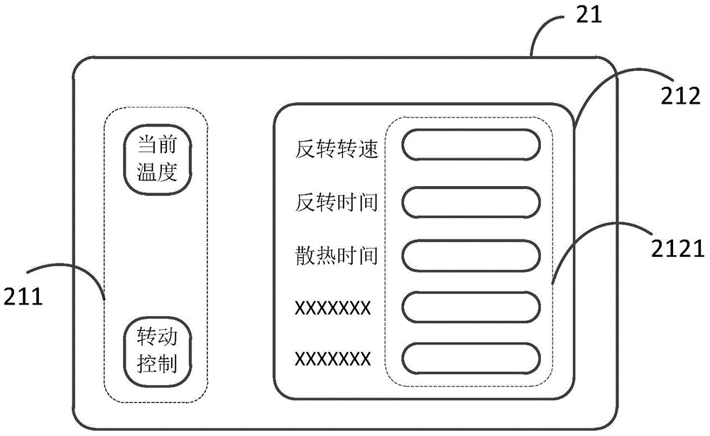
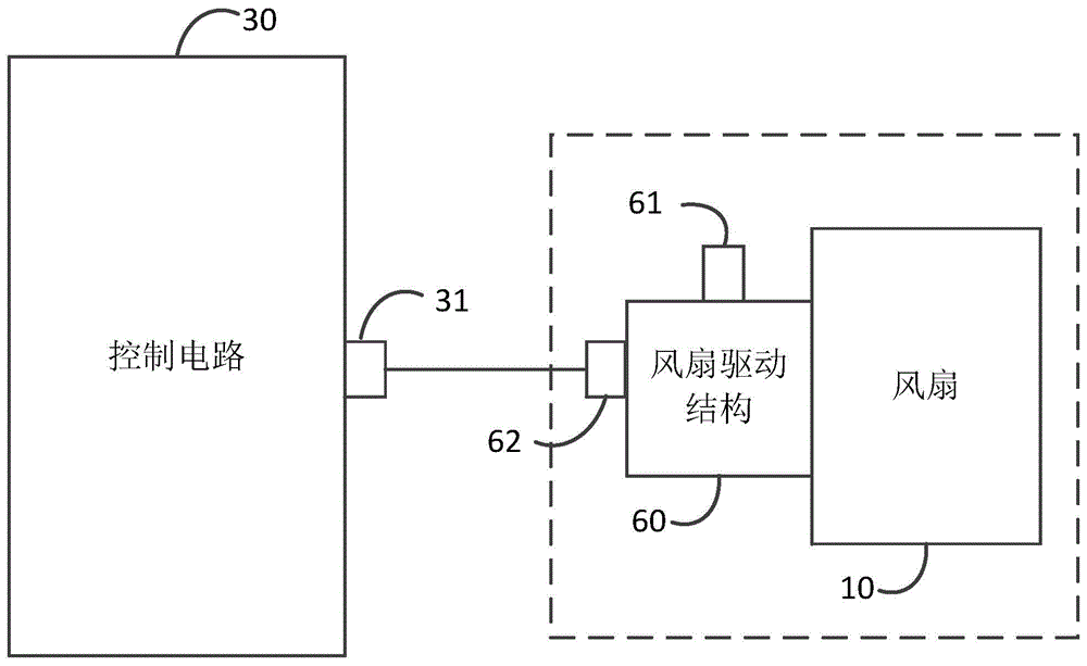
[0035] A fan control system is provided, which is applied to electronic equipment including a fan. The fan control system includes a setting module and a control circuit, wherein the setting module is located at the user end of the electronic device and is used to accept user instructions; the control instruction and setting The module and the fan are electrically connected to analyze user commands and generate corresponding fan rotation control commands based on the user commands, and the fan performs corresponding...


PUM


Abstract

The invention discloses a fan control system. The fan control system is applied to an electronic device comprising a fan. The fan control system comprises a setting module and a control circuit, the setting module is located at a user terminal of the electronic device so as to receive a user instruction, the control circuit is electrically connected with the fan and the setting module so as to analyze the user instruction, and a corresponding control signal is produced; the control signal is used for controlling the fan to rotate correspondingly. According to the fan control system, the technical problem that in the prior art, an electronic device cannot set a specific parameter of rotating of the fan is solved, and the technical effect of controlling the fan to rotate precisely is achieved.

Description

technical field [0001] The invention relates to the field of electronic technology, in particular to a fan control system. Background technique [0002] With the continuous development of science and technology, the types and functions of electronic equipment are increasing day by day, and the enhancement of functions puts forward higher requirements for the heat dissipation of electronic equipment. The heat dissipation of electronic equipment usually uses a heat dissipation module composed of heat dissipation fins to conduct heat, and at the same time uses a fan to accelerate air convection to achieve rapid heat dissipation. However, as the use time of electronic equipment increases, the dust in the environment where the electronic equipment is located will enter the interior of the electronic equipment and be adsorbed and accumulated on the heat dissipation fins and other components inside the electronic equipment. The more dust accumulates, the lower the cooling effect o...

Claims


Application Information

Patent Timeline
Patent Type & Authority Applications(China)
IPC IPC(8): F04D27/00G06F1/20
Inventor 甄庆娟
Owner LENOVO (BEIJING) LTD
Why Eureka
Try Eureka