Exhaust casing assembly used for test piece of gas compressor

A technology of assemblies, exhaust machines, applied in the direction of components of pumping devices for elastic fluids, machines/engines, pump elements, etc.

Inactive Publication Date: 2016-03-30
AECC SHENYANG ENGINE RES INST
View PDF6 Cites 13 Cited by
  • Summary
  • Abstract
  • Description
  • Claims
  • Application Information

AI Technical Summary

Problems solved by technology

The interface between the exhaust section of the test piece and the compressor test bench is fixed. When the test piece does not need a balance disc, the exhaust section can be directly connected to the stator casing of the compressor. Wh

Method used


Image

  • Exhaust casing assembly used for test piece of gas compressor
  • Exhaust casing assembly used for test piece of gas compressor

Examples


Embodiment 1

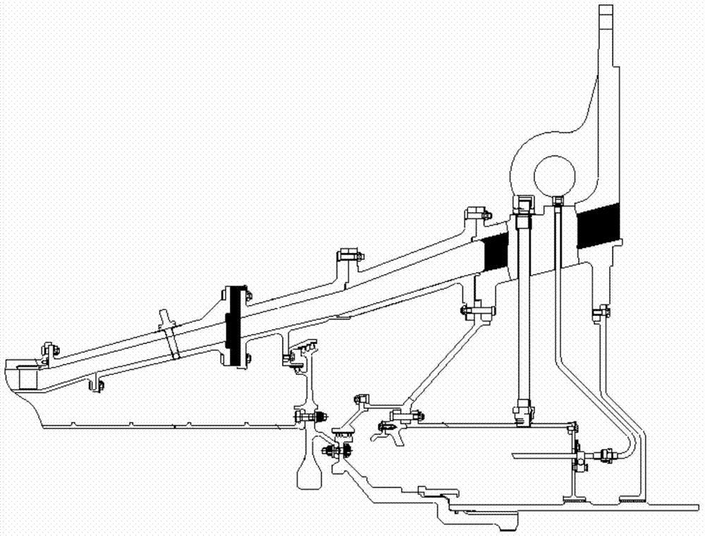
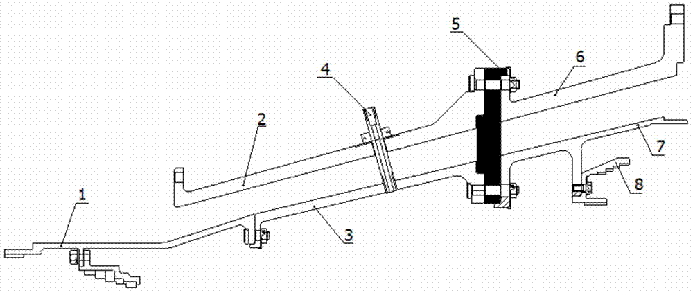
[0019] The invention provides an exhaust casing assembly that can be used for a compressor test piece, and is characterized in that: the exhaust casing assembly that can be used for a compressor test piece includes an outlet casing assembly 1, an exhaust Air outer ring front section 2, exhaust inner ring front section 3, test lead pipe 4, exhaust casing connecting ring 5, exhaust outer ring rear section 6, exhaust inner ring rear section 7, balance disk sealing ring 8;

[0020] Among them: a complete casing assembly is formed through the assembly of the exhaust casing coupling ring, the front outlet casing assembly 1 is connected to the compressor outlet, and the rear section 7 of the rear exhaust outer ring is exhausted after the compressor test piece Sectional connection, while the outlet casing assembly 1 and the rear section 7 of the exhaust outer ring are overlapped with the front and rear parts, and the components are exported casing assembly 1, the front section 3 of the...

Embodiment 2

[0028] The invention provides an exhaust casing assembly that can be used for a compressor test piece, and is characterized in that: the exhaust casing assembly that can be used for a compressor test piece includes an outlet casing assembly 1, an exhaust Air outer ring front section 2, exhaust inner ring front section 3, test lead pipe 4, exhaust casing connecting ring 5, exhaust outer ring rear section 6, exhaust inner ring rear section 7, balance disk sealing ring 8;

[0029] Among them: a complete casing assembly is formed through the assembly of the exhaust casing coupling ring, the front outlet casing assembly 1 is connected to the compressor outlet, and the rear section 7 of the rear exhaust outer ring is exhausted after the compressor test piece Sectional connection, while the outlet casing assembly 1 and the rear section 7 of the exhaust outer ring are overlapped with the front and rear parts, and the components are exported casing assembly 1, the front section 3 of the...


PUM


Abstract

An exhaust casing assembly used for a test piece of a gas compressor comprises an outlet casing assembly, a front exhaust outer ring section, a front exhaust inner ring section, a test lead, an exhaust casing connecting ring, a rear exhaust outer ring section, a rear exhaust inner ring section and a balancing disc sealing ring. The whole casing assembly is formed through assembly of the exhaust casing connecting ring. The front end of the outlet casing assembly is connected with an outlet of the gas compressor. The rear end of the rear exhaust outer ring section is connected with a rear exhaust section of the test piece of the gas compressor. The outlet casing assembly and the rear exhaust outer ring section are connected with a front component and a rear component in an overlapped mode. The outlet casing assembly, the front exhaust inner ring section, the rear exhaust outer ring section and the rear exhaust inner ring section are of cantilever structures. The exhaust casing assembly has the advantages that the exhaust casing assembly is applied to the test piece of the gas compressor which is high in pressure ratio and large is flow, the requirements for balanced axial force, exhaust flow pass switching and the like of the test piece of the gas compressor are met, and meanwhile the relative requirements for testability, assembling capacity, reliability, maintainability and the like of the test piece can also be met.

Description

technical field [0001] The invention relates to the field of compressors, in particular to an exhaust casing assembly which can be used for a compressor test piece. Background technique [0002] In order to connect the compressor test piece to the test bench safely and reliably, it is necessary to have a complete inlet and exhaust section of the test piece. The interface between the exhaust section of the test piece and the compressor test bench is fixed. When the test piece does not need a balance disc, the exhaust section can be directly connected to the stator casing of the compressor. When the test piece needs a balance disc to balance the axial When the pressure is high, it cannot be realized only by connecting the inner and outer casings with the support plate of the rear exhaust section assembly of the test piece. [0003] In the design of the rear section of the compressor test piece, the inner and outer casings forming the flow passage are connected through the sup...

Claims


Application Information

Patent Timeline
IPC IPC(8): F04D29/40F04D27/00
Inventor 张新强王华张鑫姜永强印雪梅
Owner AECC SHENYANG ENGINE RES INST
Why Eureka
Try Eureka