Testing system for material erosion resistance

A test system and anti-erosion technology, applied in analytical materials, measuring devices, weather resistance/light resistance/corrosion resistance, etc., can solve the problem of affecting the accuracy and reliability of test results, unfavorable simulation test samples, and insufficient test functions and other problems, to achieve and guarantee the results of test results, flexible test operations, and comprehensive test operations.

Inactive Publication Date: 2017-01-11
DONGFANG TURBINE CO LTD
View PDF8 Cites 7 Cited by
  • Summary
  • Abstract
  • Description
  • Claims
  • Application Information

AI Technical Summary

Problems solved by technology

[0005] At present, common material erosion resistance testing equipment is mainly a testing system with complex structure and single function. 12th), "Method and device for testing water erosion resistance of materials" (public number: CN 102621057A, public date: August 1, 2012), "test system for erosion and corrosion resistance of steam turbine blade materials and reinforced coatings" ( Publication No.: CN104502214A, Publication Date: April 8, 2015), "High-pressure Water Jet Rotating Impact Water Erosion Experimental Device" (Publication No.: CN102252927A, Publication Date: November 23, 2011), etc.
These test equipment can only perform a single water erosion test on the same sample, but cannot achieve cavitation testing. The test function is not perfect, which is not conducive to a comprehensive and true simulation test of the erosion of the sample. To achieve cavitation testing, it is necessary It is necessary to transfer the sample to the cavitation test equipment for a separate cavitation test. In this way, not only the test operation is troublesome, the cycle is long, and the cost is high, but the conversion of the sample on different test equipment will also affect the accuracy of the test results and reliability

Method used


Image

  • Testing system for material erosion resistance

Examples


Embodiment Construction

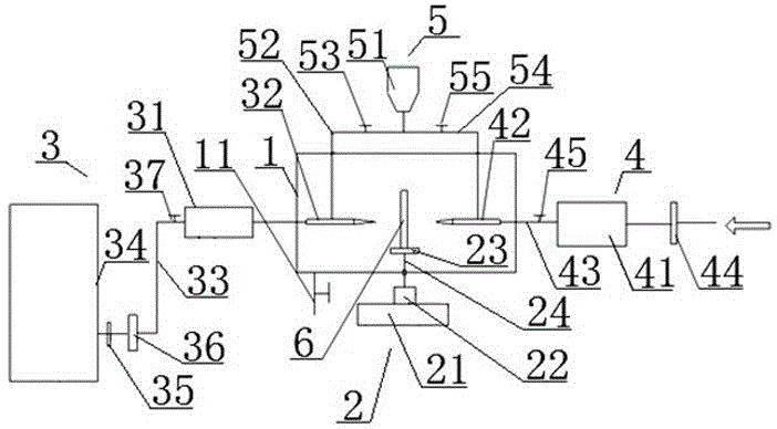
[0023] see figure 1 Shown, the present invention is the test system of material anti-erosion property, and the carrier of this material is the parts and components of industrial equipment, such as steam turbine blade, promptly the surface of blade is provided with the protection material that needs to test, and in test experiment, the steam turbine blade Part of it is sample 6, that is, sample 6 is a sample of the blade. The test system includes a test chamber 1 , a sample control mechanism 2 , a water erosion test part 3 , a cavitation test part 4 and a particle addition part 5 .

[0024] Wherein, the test chamber 1 is a space for the entire test operation, which is in the shape of a box. The center of the test chamber 1 is used to clamp the sample 6 through the sample control mechanism 2; the two opposite side walls of the test chamber 1 are used to arrange the water erosion test part 3 and the cavitation test part 4; There is a sewage outlet, and a sewage valve 11 is seal...


PUM


Abstract

The invention discloses a testing system for material erosion resistance. The system comprises a testing chamber, a water erosion testing portion, a cavitation testing portion and a particle adding portion. The testing chamber is a testing operation space and is used for clamping a sample. The water erosion testing portion is mainly composed of a water tank, a high pressure water generator and a high pressure water nozzle which are sequentially connected. The high pressure water nozzle extends into the testing chamber and corresponds to the sample inside the testing chamber. The cavitation testing portion is mainly composed of an air compressor and a high pressure gas nozzle which are sequentially connected. The high pressure nozzle extends into the testing chamber and corresponds to the sample inside the testing chamber. The particle adding portion is mainly composed of a particle storage tank and a particle conveying pipe. One end of the particle conveying pipe is connected with the particle storage tank, the other end of the particle conveying pipe is connected with the water erosion testing portion and/or the cavitation testing portion. A particle flow control valve is arranged on the particle conveying pipe. The testing system can perform comprehensive, accurate and reliable testing on the erosion performance of a material to be tested.

Description

technical field [0001] The invention mainly relates to material performance testing equipment, in particular to a material erosion resistance testing system. Background technique [0002] During the operation of the steam turbine unit, when the saturated steam in the low-pressure cylinder expands and does work, a part of the steam will cross the saturation line and condense into water droplets, which will increase the humidity in the low-pressure cylinder, and the moving blades will work in a wet steam environment for a long time , subject to constant erosion and impact of water droplets, vulnerable to water erosion. In particular, the blades of the last stage of the low-pressure cylinder are more obvious. Their working environment is harsher, the humidity is higher, and the linear speed of the blade tip is higher, so they are subject to greater centrifugal force, steam force, and exciting force. It is often mixed with a small amount of oxide scale particles that are droppe...

Claims


Application Information

Patent Timeline
Patent Type & Authority Applications(China)
IPC IPC(8): G01N17/00
CPCG01N17/00
Inventor 梁君李小江薛慧婷李霁陈明东白润东宋冬梅杨德存
Owner DONGFANG TURBINE CO LTD
Why Eureka
Try Eureka