
Flatness detecting device

A flatness detection and leveling technology, applied in measuring devices, optical devices, instruments, etc., can solve problems such as low efficiency and easy misjudgment

Inactive Publication Date: 2016-03-30
GUANGDONG EVERWIN PRECISION TECH
View PDF6 Cites 5 Cited by
  • Summary
  • Abstract
  • Description
  • Claims
  • Application Information

AI Technical Summary

Problems solved by technology

[0004] Based on this, it is necessary to provide a flatness detection device with high detection efficiency and low misjudgment for the problems of low efficiency and easy misjudgment in the existing flatness detection process

Method used


Image

  • Flatness detecting device
  • Flatness detecting device
  • Flatness detecting device

Examples


Embodiment Construction

[0019] In order to facilitate the understanding of the present invention, the present invention will be described more fully below with reference to the associated drawings. Preferred embodiments of the invention are shown in the accompanying drawings. However, the present invention can be embodied in many different forms and is not limited to the embodiments described herein. On the contrary, these embodiments are provided to make the understanding of the disclosure of the present invention more thorough and comprehensive.

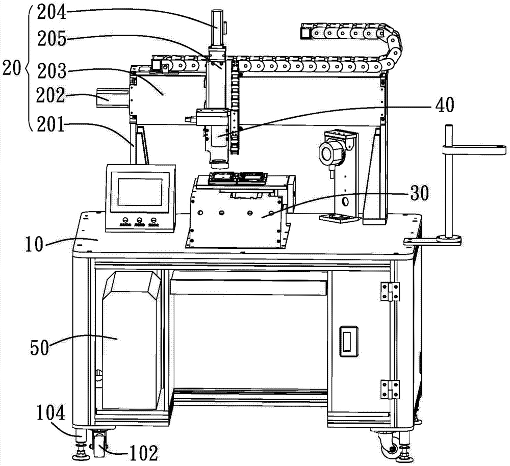
[0020] see figure 1 , The flatness detection device provided by the present invention includes a workbench 10 , an assembly frame 20 , a detection platform 30 , a CCD (Charge-coupled Device, charge-coupled device) detector 40 and a control device 50 .

[0021] The workbench 10 is used to provide a place for flatness detection, and the assembly frame 20 , the detection platform 30 , the CCD detector 40 and the control device 50 are all arranged on the wo...


PUM


Abstract

The invention relates to a flatness detecting device. The flatness detecting device includes a work table, a total assembly rack arranged on the work table, a detection platform which is arranged on the work table and includes a bearing surface for bearing and fixing products to be tested, a CCD detector which is arranged on the total assembly rack and is located above the detection platform, and a control device used for turning on and controlling the CCD detector to perform flatness detection; the bearing surface is provided with a plurality of upright columns which protrude along a Z-axis direction; and the top surfaces of the upright columns are provided with tilt light reflecting mirror surfaces, included angles being formed between the tilt light reflecting mirror surfaces and a horizontal plane being acute angles. The flatness detecting device has the advantages of high detection efficiency and little possibility of causing misjudgment.

Description

technical field [0001] The invention relates to a product detection device, in particular to a product flatness detection device. Background technique [0002] At present, manufacturers of plastic parts such as mobile phone casings and small home appliances need to test the flatness of the products when they involve injection molding products with steel sheets, zinc alloy brackets and other metals. [0003] The traditional detection method is to manually place the product flat on the marble platform, and use a feeler gauge or a height gauge for detection, because when using a feeler gauge or a height gauge, it needs to measure from multiple measurement points, and there are many measurement points , the time required for detection is also long, so the detection efficiency is low, it cannot meet the modern production scale, and it is impossible to carry out rapid and large-scale detection, and the unstable factors of manual detection are easy to cause misjudgment. Contents ...

Claims


Application Information

Patent Timeline
IPC IPC(8): G01B11/30
CPCG01B11/303
Inventor 陈勇军李瑞林
Owner GUANGDONG EVERWIN PRECISION TECH
Learn More