A Constant Volume Combustion Device for Studying Spray Form and Its Microscopic Characteristics

A constant volume combustion and microscopic technology, applied in the direction of internal combustion engine testing, etc., can solve the problem that the structure of constant volume combustion projectile is not optimized enough, cannot effectively measure the macroscopic morphology and microscopic characteristics of various fuel sprays synchronously, and cannot apply multiple fuel injection systems, etc. problems, to achieve the effect of improving observation and shooting effects, improving observation data and measurement effects, and increasing data collection rate

Inactive Publication Date: 2018-12-04
TIANJIN UNIV
View PDF9 Cites 0 Cited by
  • Summary
  • Abstract
  • Description
  • Claims
  • Application Information

AI Technical Summary

Problems solved by technology

[0005] The problem to be solved by the present invention is that the structure of the existing constant-volume incendiary bombs is not optimized enough, which leads to the inability to cooperate with advanced optical measurement equipment, and the inability to apply various fuel injection systems, so that it is impossible to effectively simultaneously measure the macroscopic forms and microscopic characteristics of various fuel sprays To solve the technical problems, a constant-volume combustion device for studying spray morphology and its microscopic characteristics is provided. ) and other modern optical measuring instruments are used together to achieve the purpose of not only observing the macroscopic shape of the spray but also measuring its microscopic characteristics, and by setting the synchronization signal, the macroscopic topography and its characteristics of one or more sprays can be obtained at the same time. Microscopic information, so as to realize further research on the fragmentation and atomization of fuel

Method used


Image

  • A Constant Volume Combustion Device for Studying Spray Form and Its Microscopic Characteristics
  • A Constant Volume Combustion Device for Studying Spray Form and Its Microscopic Characteristics
  • A Constant Volume Combustion Device for Studying Spray Form and Its Microscopic Characteristics

Examples


Embodiment Construction

[0028] Below in conjunction with accompanying drawing, the present invention will be further described:

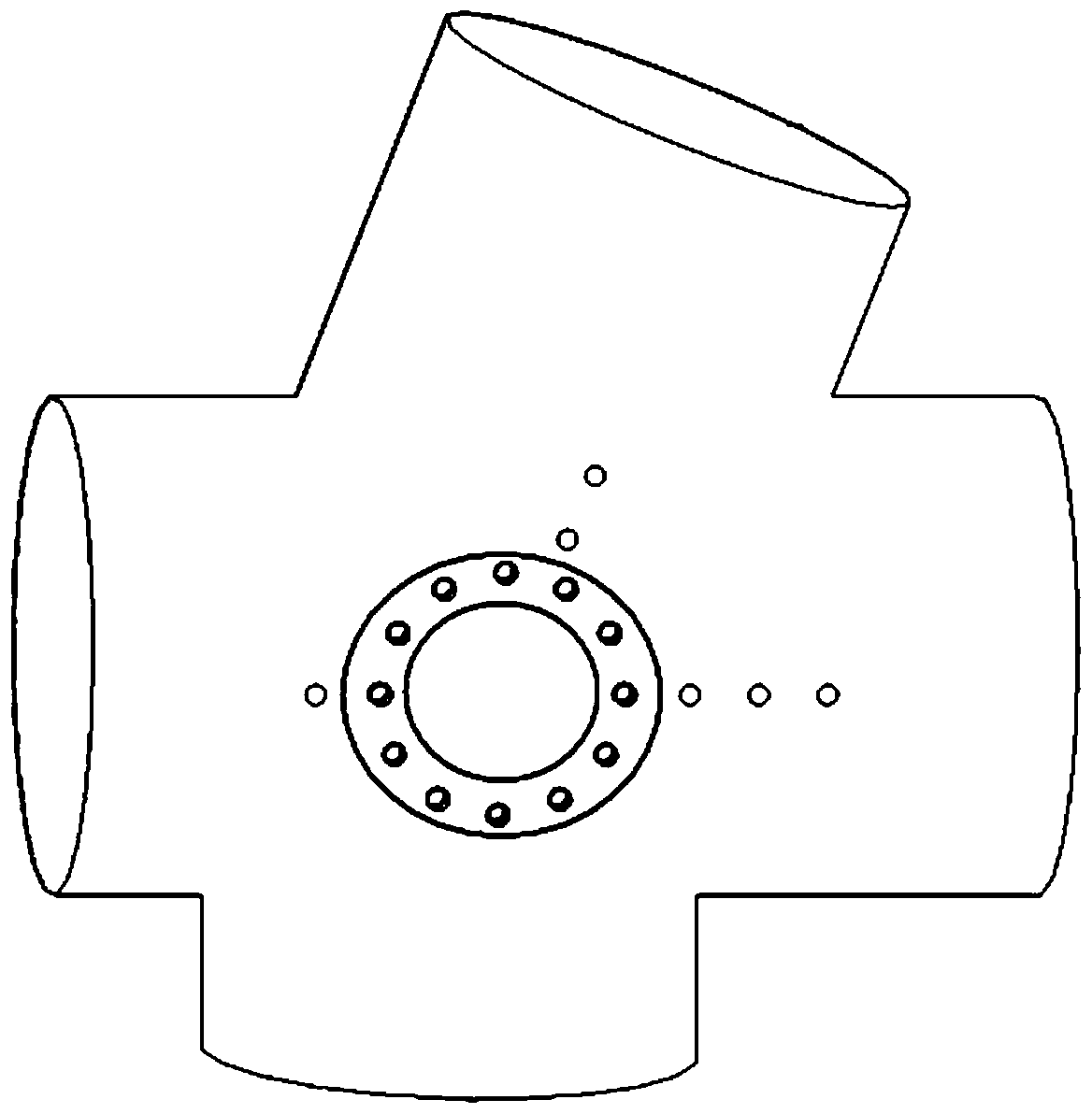
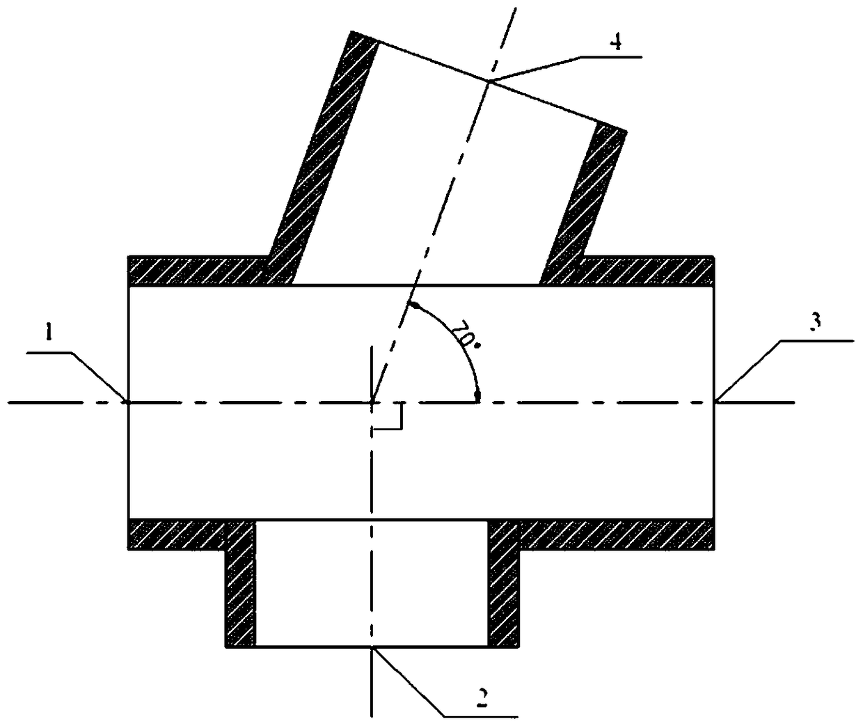
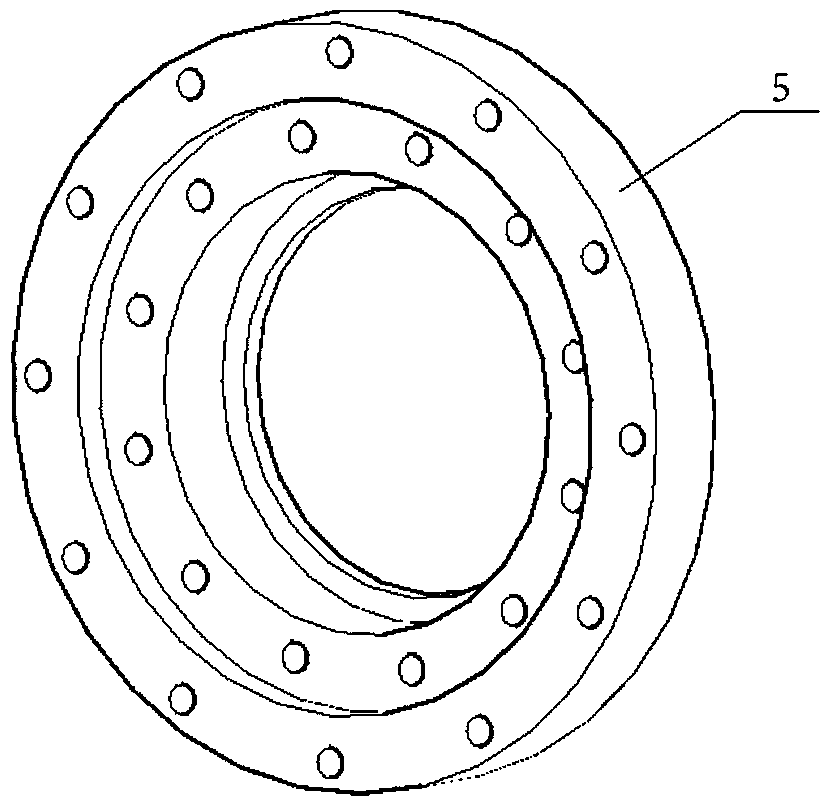
[0029] A constant-volume combustion device for studying the spray form and its microscopic characteristics, including a combustion bomb installed inside the box, such as figure 1 As shown, the incendiary bomb body is provided with four observation holes in the shape of through holes, the axes of the observation holes are all on the same horizontal plane, and the angle between the axes of the two observation holes is 180°, and the axes of the other two observation holes The angle between them is 160°; if figure 2 As shown, optical observation windows 1, 2, 3, and 4 are correspondingly arranged on the observation holes, such as image 3 , Figure 4 and Figure 5 As shown, the optical observation window is composed of port flange 5, optical glass and glass gland 6. The port flange 5 is installed in the observation hole through the inner hexagonal bolt, the optical glass i...


PUM


Abstract

The invention discloses a constant-volume burning device for studying a spraying form and micro-characteristics of the spraying form, and the device comprises a burning elastic body disposed in a box body. The burning elastic body is provided with four observation holes which are shaped like through holes. The axes of the observation holes are located in the same horizontal plane, wherein the angle between the axes of two observation holes is 180 degrees, and the inclined angle between the axes of the other two observation holes is 160 degrees. The observation holes are provided with optical observation windows, and each optical observation window consists of a port flange, optical glass, and a glass gland. An oil sprayer system is disposed exactly above the central part of the burning elastic body. The device can be used cooperatively along with various types of modern optical measurement instruments, thereby achieving a purpose of observing a spraying macro-form and measuring the micro-characteristics of the spraying form. Moreover, the device can obtain macro-form images and micro-characteristic information of one or more spraying beams at the same time through the arrangement of a synchronization signal, thereby achieving the further research of the breaking atomization of fuel.

Description

technical field [0001] The invention relates to the field of research on spray characteristics of internal combustion engines, in particular to a constant-volume combustion device for observing the macroscopic morphology of the spray and measuring the microscopic characteristics of the spray Background technique [0002] In the field of internal combustion engines, the atomization process of fuel directly affects the combustion and emission performance, thereby contributing to the alleviation of energy and environmental problems. Therefore, for internal combustion engine researchers, it is necessary to obtain fuel spray characteristics (jet breakage length, spray cone angle, oil droplet size and velocity, etc.) and its relationship with surrounding environmental parameters (pressure, temperature, ambient gas type and density, etc.) , and then establish the kinetic mechanism of fuel atomization reaction, and finally provide basic data for engine spray simulation and optimizat...

Claims


Application Information

Patent Timeline
Patent Type & Authority Patents(China)
IPC IPC(8): G01M15/04
CPCG01M15/04
Inventor 王玉龙杜青白富强杨贤郭瑾朋杨子明
Owner TIANJIN UNIV
Why Eureka
Try Eureka