
Detonation tube structure of a rotary pulse detonation engine

A technology of pulse detonation and detonation tube, which is applied to mechanical equipment, intermittent injection devices, etc., can solve the problems of shortening the detonation tube length of detonation engines, high oil and gas mixing degree, and low fuel utilization rate, etc. The effect of full combustion, reduced weight, increased reliability

Active Publication Date: 2018-10-02
西安飞动科技有限公司
View PDF5 Cites 2 Cited by
  • Summary
  • Abstract
  • Description
  • Claims
  • Application Information

AI Technical Summary

Problems solved by technology

This technology adopts a self-supply air scheme, the fuel injection direction is radial, and the oil-gas mixing degree is high, which can effectively shorten the length of the detonation tube of the detonation engine and improve the problem of low fuel utilization.

Method used


Image

  • Detonation tube structure of a rotary pulse detonation engine
  • Detonation tube structure of a rotary pulse detonation engine

Examples


Embodiment Construction

[0016] The present invention will be further described now in conjunction with accompanying drawing:

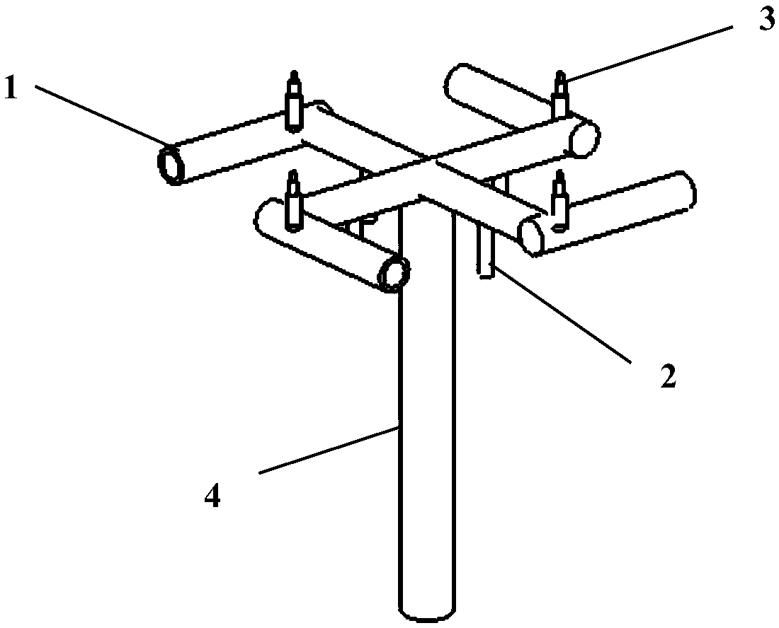
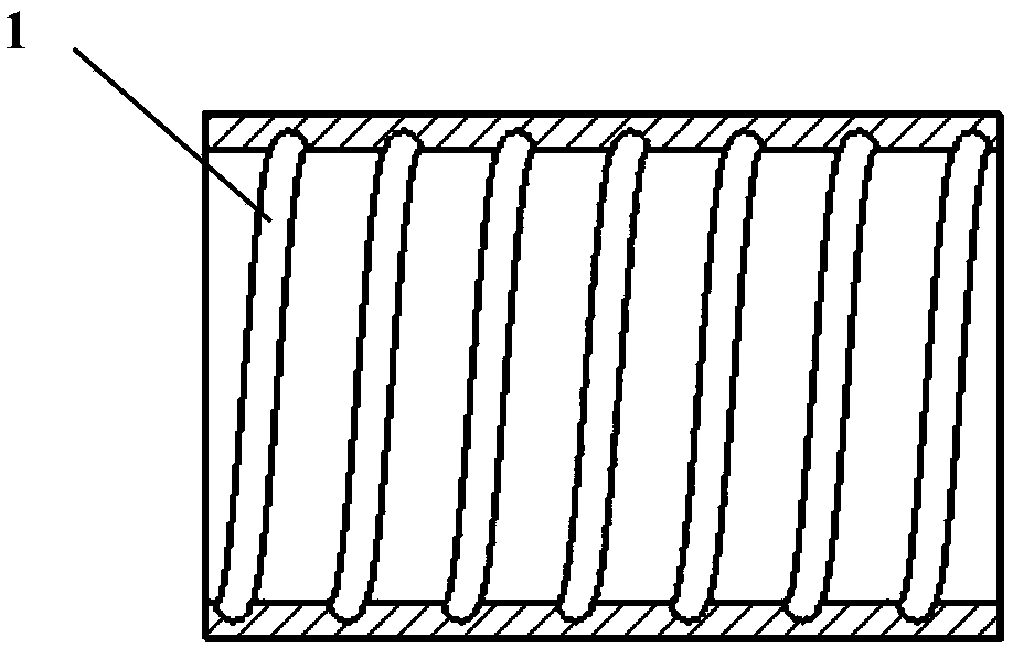
[0017] combine figure 1 and figure 2 , The invention provides a novel detonation tube structural plate of a rotary pulse detonation engine capable of stably outputting shaft work. figure 2 It is a structural schematic diagram of the spiral groove on the inner wall of the detonation tube of the rotary pulse detonation engine.

[0018] figure 1 It is a structural schematic diagram of a rotary detonation tube. The detonation tube of a rotary air-breathing pulse detonation engine includes 1-detonation tube, 2-fuel injection tube, 3-spark plug and 4-power output shaft (intake tube). The 1-detonation tube is distributed in a swastika structure, and there are 4 1-detonation tubes, the length of which is the same depending on the design. In addition, there is a straight tube structure at the entrance of the 1-detonation tube for air supply. 2-The fuel injection pipe is install...


PUM


Abstract

The invention provides a detonation tube structure of a rotary pulsed detonation engine. A swastika-shaped rotational structure enables airflow to form radial and circumferential secondary flow in a pipeline; and oil mist sprayed by oil spray tubes are perpendicular to the direction of main flow, and the atomization speed and the oil-gas mixing degree can be increased. After oil and gas are mixed, combustible mixed gas is ignited by sparking plugs, and deflagration is caused. Since the combustible gas speed is far greater than the gas flow speed of inlets of detonation tubes, the radial and circumferential secondary flow of the detonation tubes can be enhanced; and spiral grooves in the portions, behind the corresponding sparking plugs, of the inner walls of the detonation tubes can increase the tube inner turbulivity and enable the combustible gas flowing through to further rotate in the circumferential direction, accordingly the converting distance from deflagration to detonation is shortened, the lengths of the detonation tubes are shortened, and the working reliability of the detonation tubes are improved. In addition, since the four detonation tubes work at the same time, the power output range is wider, and adjustment is more flexible.

Description

technical field [0001] The invention belongs to the field of pulse detonation engines, and in particular relates to a detonation tube structure of a rotary pulse detonation engine which utilizes detonation waves to generate thrust and output shaft work. Background technique [0002] The pulse detonation engine is a new type of power device developed based on the new concept of detonation combustion. It has the advantages of simple structure, small size, wide application range, low cost, and a thrust-to-weight ratio of up to 20. Based on the above advantages, the pulse detonation engine can be applied to the power plant of small aircraft and unmanned aerial vehicles, and can also be used as the power of the propeller tip jet rotorcraft. It can also be developed into a power propulsion device for high-altitude aircraft in the future. [0003] The basic principle of the pulse detonation engine to output power is to use the periodic detonation waves generated by the detonation t...

Claims


Application Information

Patent Timeline
Patent Type & Authority Patents(China)
IPC IPC(8): F02K7/02
CPCF02K7/02
Inventor 张群寇睿李承钰宋亚恒黎超超李逸飞
Owner 西安飞动科技有限公司
Learn More