Thin inductor structure and manufacturing method

An inductance and thin technology, applied in the field of inductance, can solve the problems of low efficiency and complicated manufacturing process of thin inductance structure, and achieve the effect of increasing output, simplifying manufacturing process and improving work efficiency

Active Publication Date: 2017-09-01
DONGGUAN JIAN GUAN PLASTIC ELECTRONICS +2
View PDF6 Cites 0 Cited by
  • Summary
  • Abstract
  • Description
  • Claims
  • Application Information

AI Technical Summary

Problems solved by technology

[0004] In view of this, the present invention aims at the deficiencies of the prior art, and its main purpose is to provide a thin inductor structure and a manufacturing method, which can effectively solve the problems of cumbersome manufacturing process and low efficiency of the existing thin inductor structure
[0006] In view of this, the present invention aims at the deficiencies of the prior art, and its main purpose is to provide a thin inductor structure and a manufacturing method, which can effectively solve the problems of cumbersome manufacturing process and low efficiency of the existing thin inductor structure

Method used


Image

  • Thin inductor structure and manufacturing method
  • Thin inductor structure and manufacturing method
  • Thin inductor structure and manufacturing method

Examples


Embodiment Construction

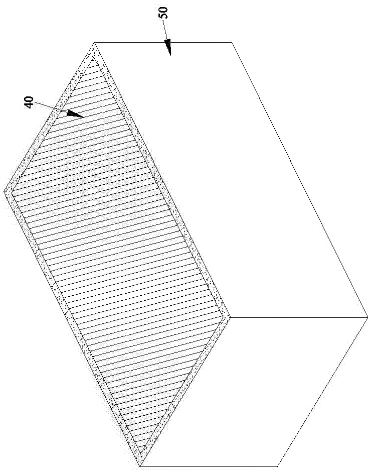
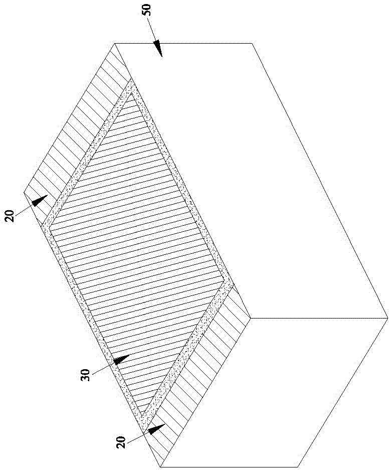
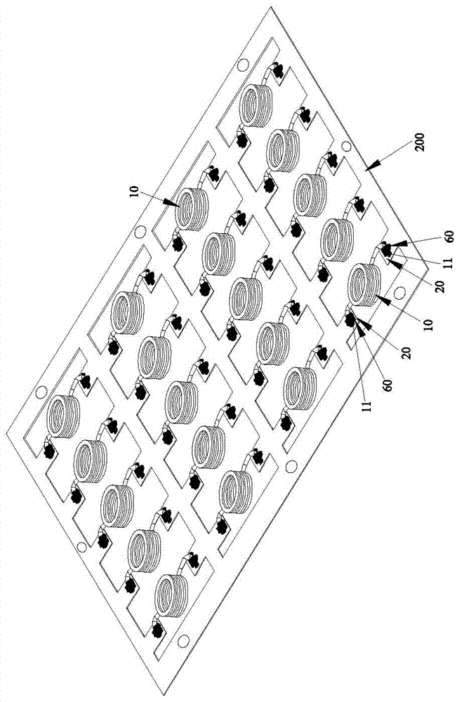
[0034] Please refer to Figure 1 to Figure 8 As shown, it shows the specific structure of the preferred embodiment of the present invention, including a coil 10 , two electrode terminals 20 , a first magnetically conductive sheet 30 , a second magnetically conductive sheet 40 and a body 50 .

[0035] The coil 10 has two pins 11. Specifically, the coil 10 is composed of a copper wire and an insulating layer covering the copper wire.

[0036] The two electrode terminals 20 are arranged at intervals, and the two electrode terminals 20 are respectively electrically connected to the aforementioned two pins 11 .

[0037] The first magnetically conductive sheet 30 is disposed between the two electrode terminals 20 and below the coil 10 , and the second magnetically conductive sheet 40 is disposed above the first magnetically conductive sheet 30 .

[0038] The main body 50 is a mixture of iron powder and plastic. The main body 50 covers the coil 10 and adheres the first magnetic cond...


PUM


Abstract

The invention discloses a thin inductor structure and a manufacturing method thereof. The thin inductor structure comprises a coil, two electrode tips, a first magnetic conductive plate, a second magnetic conductive plate and a body, wherein the coil comprises two pins; the two electrode tips are electrically connected with the two pins respectively; the first magnetic conductive plate is arranged between the two electrode tips and is located below the coil; the second magnetic conductive plate is arranged above the coil corresponding to the first magnetic conductive plate; and the body coats the coil and sticks the first magnetic conductive plate, the second magnetic conductive plate and the two electrode tips. The two pins of the coil are temporarily adhered to the two electrode tips of a preset customized lead frame by directly utilizing tin paste; tin paste melting is carried out in a reflow oven; and the two pins of the coil and the two electrode tips on the lead frame are welded and fixed, so that welding actions do not need to be carried out one by one between the two pins of the coil and the two electrode tips on the lead frame; the target of simplifying the process is reached; the work efficiency is effectively improved; and the output benefits are improved.

Description

technical field [0001] The invention relates to the technology in the field of inductors, in particular to a thin inductor structure and a manufacturing method. Background technique [0002] In the known thin inductor structure, although there are many types of bodies, the connection and fixation between the coil in the structure and the first wire and the second wire end on the lead frame are all done by welding, for example, as shown in the figure below : U.S. No. 6,204,744 patent of invention, please refer to shown in its No. 1B figure and No. 1 C figure, can see the lead frame 32 of the first lead 16 on the lead frame 32 and the lead frame 32 of the second lead 18 in the figure The two ends 34 , 38 are combined and fixed with the inner end 26 and the outer end 28 of the coil 24 respectively by means of welding. In addition, as shown in Figures 3, 4, and 5 of Taiwan Approved Publication No. 201234395 Patent, the two folded legs 1 1 of the conductive coil 1 0 and the weld...

Claims


Application Information

Patent Timeline
Patent Type & Authority Patents(China)
IPC IPC(8): H01F17/04H01F27/28H01F27/29H01F41/10
CPCH01F17/043H01F27/2823H01F27/292H01F41/10
Inventor 徐钰钦
Owner DONGGUAN JIAN GUAN PLASTIC ELECTRONICS
Why Eureka
Try Eureka