
Motor stator structure and motor

A technology for motor stator and stator punching, which is applied to the shape/pattern/structure of the magnetic circuit, static components of the magnetic circuit, etc., can solve the problems affecting assembly, stator deformation, etc., and achieve the effect of reducing the amount of deformation

Active Publication Date: 2016-03-30
GREE ELECTRIC APPLIANCES INC +1
View PDF7 Cites 5 Cited by
  • Summary
  • Abstract
  • Description
  • Claims
  • Application Information

AI Technical Summary

Problems solved by technology

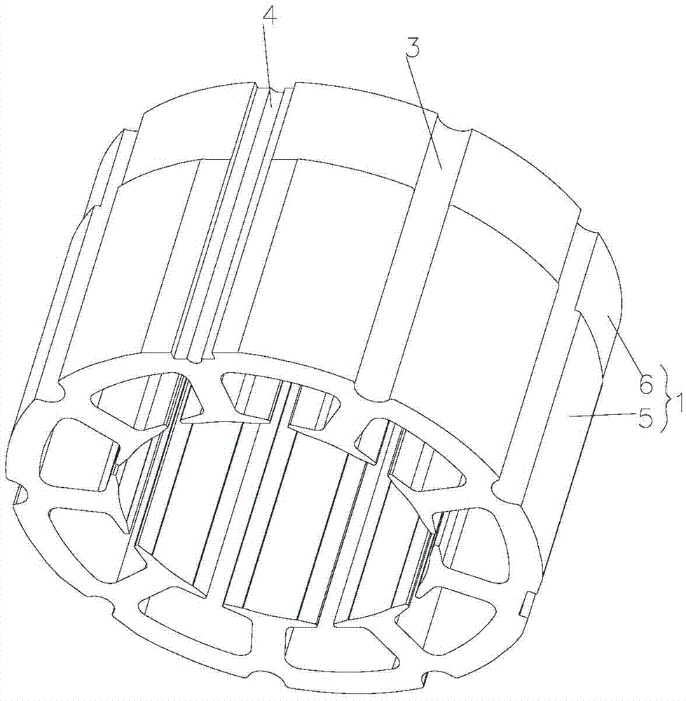
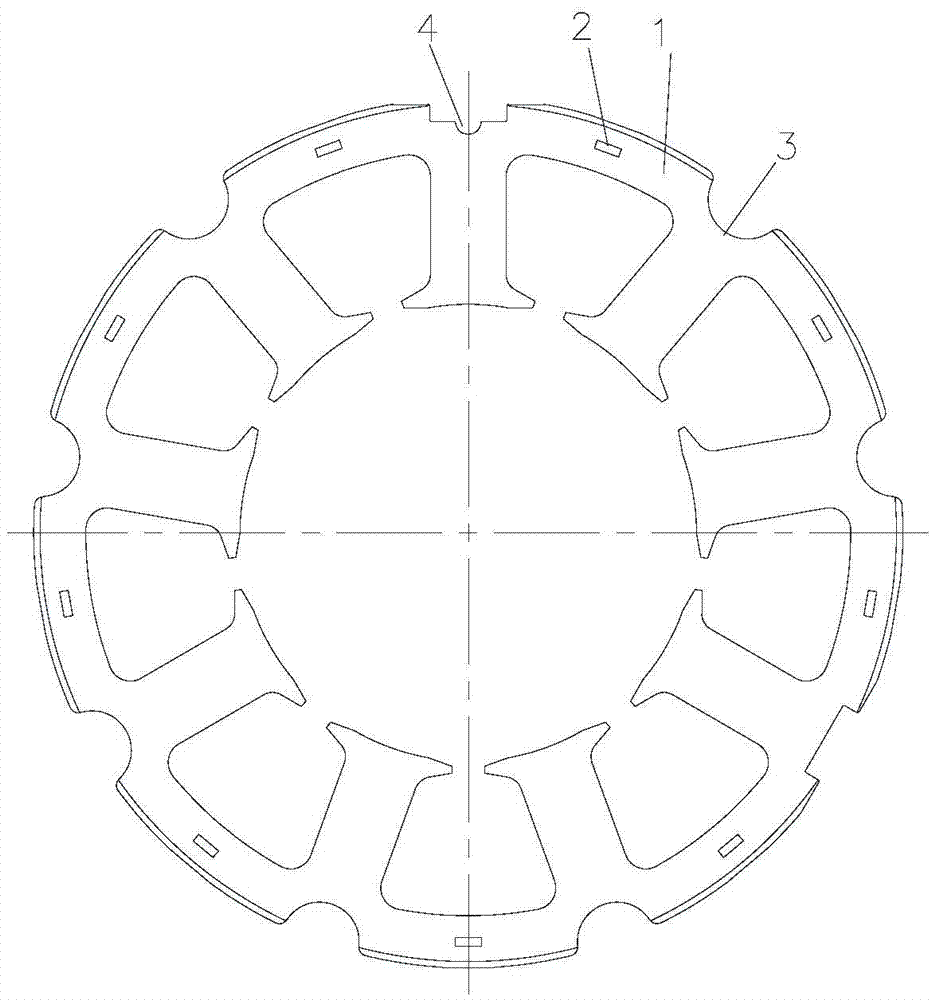
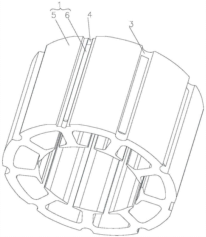
[0004] In the embodiment of the present invention, a motor stator structure and motor are provided to solve the problem in the prior art that the stator is deformed due to the stress concentration on the stator and affects the assembly

Method used


Image

  • Motor stator structure and motor
  • Motor stator structure and motor
  • Motor stator structure and motor

Examples


Embodiment Construction

[0024] The present invention will be described in further detail below in conjunction with the accompanying drawings and specific embodiments, but not as a limitation of the present invention.

[0025] Please refer to Figure 1 to Figure 7 As shown, according to the embodiment of the present invention, the stator structure of the motor includes a stator core 1 and a skeleton. The stator core 1 is provided with a flow hole 3 and a positioning groove 4 matched with the skeleton. The positioning groove 4 is arranged at the bottom of the flow hole 3. The stator core 1 also has a stress adjustment structure.

[0026] Among them, the stator core is formed by stacking conventional stator punches, and is buckled together by buckle points. After the stator is laminated, it is assembled with the skeleton, and then the subsequent processing is carried out; among them, the commonly used skeleton and stator assembly methods mostly use the buckle point design of the skeleton, and the buckl...


PUM


Abstract

The invention discloses a motor stator structure and a motor. The motor stator structure comprises a stator iron core (1) and a framework, wherein through holes (3) and locating slots (4) matching the framework are formed in the stator iron core (1), the locating slots (4) are formed in the bottoms of the through holes (3), and the stator iron core (1) is further provided with a stress adjustment structure. According to the motor stator structure provided by the invention, a problem that installation is affected by stator deformation due to concentration of stress on the stator in the prior art can be solved.

Description

technical field [0001] The invention relates to the technical field of motors, in particular to a motor stator structure and a motor. Background technique [0002] In the existing technology, in order to meet the flow area and the installation requirements of the skeleton when designing the trimming of the stator core, a large flow hole is opened in the stator yoke, resulting in a relatively thin part of the yoke and insufficient strength. In addition, the flow hole is also used for The positioning groove of the frame will cause deformation of the yoke when mating with the frame. [0003] Since the stator yoke is relatively thin locally, after the thermal sleeve with the compressor shell is completed, the stress on the yoke will be relatively concentrated, and the local iron loss of the stator will increase, which will affect the energy efficiency. affect the assembly of the stator. Contents of the invention [0004] Embodiments of the present invention provide a motor s...

Claims


Application Information

Patent Timeline
Patent Type & Authority Applications(China)
IPC IPC(8): H02K1/12
CPCH02K1/12
Inventor 周博孙文娇曾学英陈彬
Owner GREE ELECTRIC APPLIANCES INC
Learn More