Shaft system structure and assembly method for electric motor

An assembly method and shafting technology, which are used in electromechanical devices, manufacturing of motor generators, magnetic circuit shape/style/structure, etc., can solve the problem of difficulty in ensuring the coaxiality of three-section shafts, and achieve easy to ensure assembly coaxiality. , Improve the effect of simple processing and assembly

Active Publication Date: 2018-06-12
GREE ELECTRIC APPLIANCES INC +1
View PDF6 Cites 0 Cited by
  • Summary
  • Abstract
  • Description
  • Claims
  • Application Information

AI Technical Summary

Problems solved by technology

[0009] The object of the present invention is to address the above-mentioned defects and propose a motor shafting structure and assembly method to solve the problem that the coaxiality is difficult to guarantee when the three-section shaft is hot-fitted

Method used


Image

  • Shaft system structure and assembly method for electric motor
  • Shaft system structure and assembly method for electric motor
  • Shaft system structure and assembly method for electric motor

Examples


Embodiment Construction

[0046] In order to make the purpose, technical solution and advantages of the present invention clearer, the technical solution of the present invention will be clearly and completely described below in conjunction with specific embodiments of the present invention and corresponding drawings. Apparently, the described embodiments are only some of the embodiments of the present invention, but not all of them. Based on the embodiments of the present invention, all other embodiments obtained by persons of ordinary skill in the art without making creative efforts belong to the protection scope of the present invention.

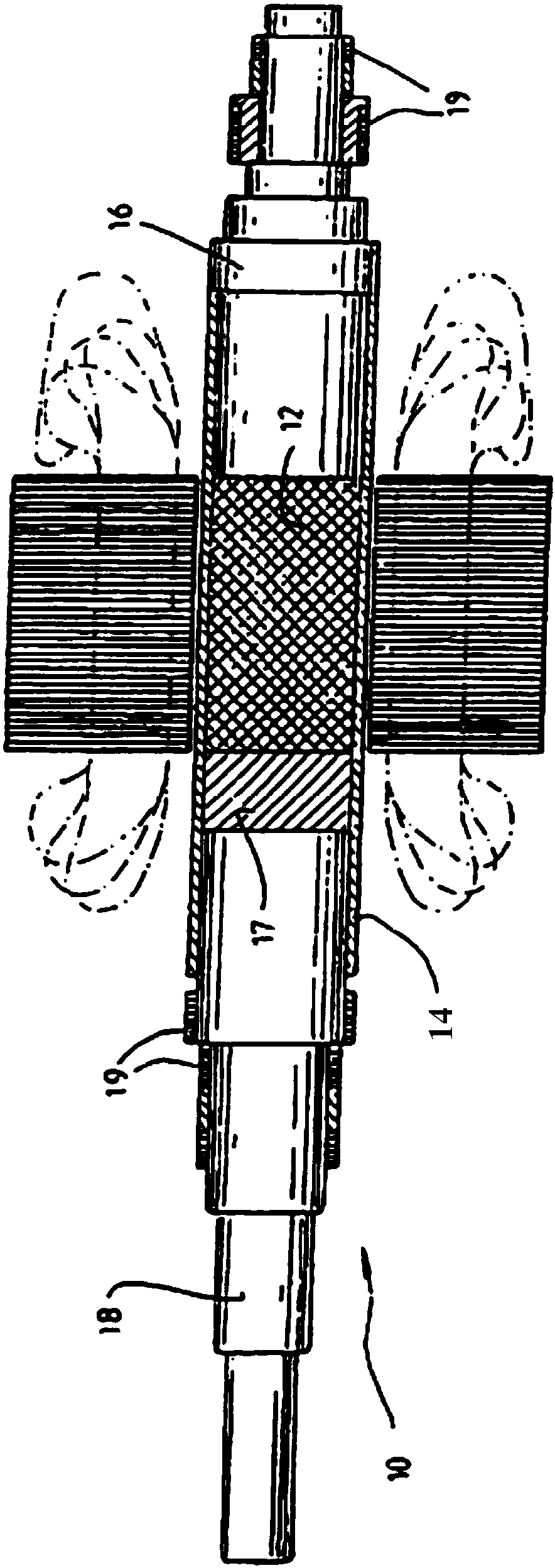
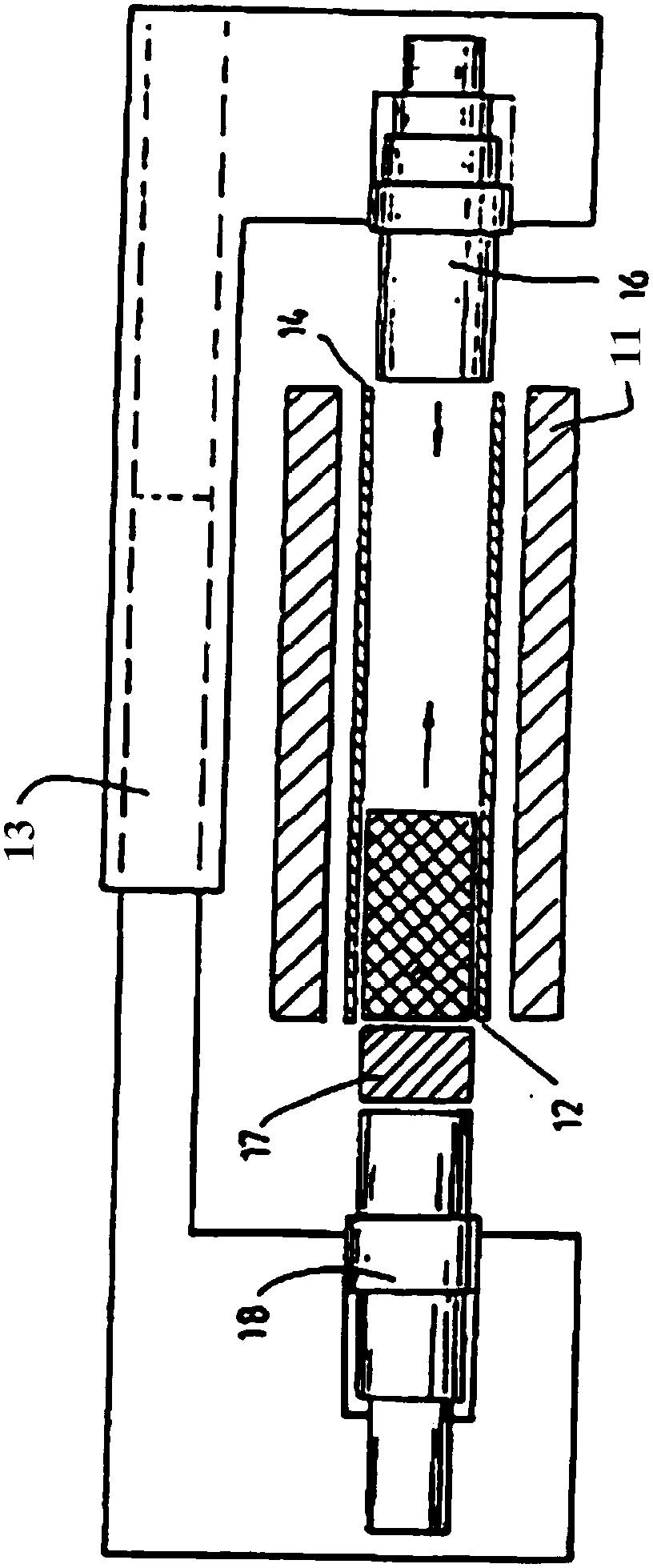
[0047] According to an embodiment of the present invention, such as Figure 5 As shown, a shafting structure for a motor is provided. The shafting structure for the motor includes: a front shaft 62 , a rear shaft 63 , an annular magnetic steel 61 and an alloy sheath 60 . Wherein, the rear shaft 63 includes a first shaft section 631 and a second shaft section 633...


PUM


Abstract

The invention discloses a shafting structure for a motor, and an assembling method. The shafting structure comprises a front-segment shaft (62), a rear-segment shaft (63), annular magnetic steel (61) and an alloy sheath (60), wherein the rear-segment shaft (63) successively comprises a first shaft joint (631) and a second shaft joint (633) from front to back, and the diameter of the first shaft joint (631) is smaller than that of the second shaft joint (633); the annular magnetic steel (61) sleeves the first shaft joint (631) of the rear-segment shaft (63); the external diameter of the rear end of the front-segment shaft (62) is the same as the external diameter of the annular magnetic steel (61); and the alloy sheath (60) sleeves the front-segment shaft (62) and the annular magnetic steel (61). According to the scheme provided by the invention, the shafting structure and the assembling method overcome the defects of complex structure, large assembling difficulty, poor safety and the like in the prior art and also have the advantages of simple structure, small assembling difficulty and good safety.

Description

technical field [0001] The invention relates to the technical field of electric motors, in particular to a shafting structure and an assembly method for an electric motor, in particular to a shafting structure and an assembly method for an ultra-high-speed electric motor. Background technique [0002] The motor is composed of two parts, the rotor and the stator, and is an electromagnetic device that realizes the conversion or transmission of electric energy according to the law of electromagnetic induction. The motor rotor is the rotating part in the motor. [0003] Generally, a rotor whose speed is above 1000 rpm or exceeds the first-order critical speed of the rotor can be regarded as a high-speed rotor. In the patent document with the patent application number "98802132.3", a rotor for a high-speed machine, a manufacturing method thereof, and a motor having the rotor are disclosed. Among them, such as figure 1 , figure 2 As shown, in a high-speed machine rotor and it...

Claims


Application Information

Patent Timeline
Patent Type & Authority Patents(China)
IPC IPC(8): H02K1/27H02K15/00H02K15/03H02K7/00
CPCH02K1/2706H02K7/003H02K15/00H02K15/03
Inventor 张芳胡余生刘健宁龚高贾金信郭长光李广海田思园
Owner GREE ELECTRIC APPLIANCES INC
Why Eureka
Try Eureka