Magnetic transmission device having coupling, separation and reunion and speed regulation functions and mounting method thereof

A magnetic transmission and functional technology, applied in permanent magnet clutches/brakes, asynchronous inductive clutches/brakes, electromechanical devices, etc., can solve problems affecting the quality of power grid power supply, motor overheating, grid frequency harmonic interference, etc.

Inactive Publication Date: 2016-03-30
LIAONING MINGDE MAGNETIC POWER TECH CO LTD
View PDF6 Cites 10 Cited by
  • Summary
  • Abstract
  • Description
  • Claims
  • Application Information

AI Technical Summary

Problems solved by technology

[0002] When the existing motor starts to drive under high load, due to the excessive starting current, it will generate a large instantaneous current to the grid and the motor, which will easily cause the motor to overheat and cause electrical equipment failure
At present, the best solution is to use frequency conversion speed regulation control to solve the problem of motor overheating damage, but it has the following problems in the operation process: 1) The structure of the inverter equipment is complex, and it has high requirements on the site environment, which must be cleaned and ventilated Work in a good environment; 2) The inverter will generate harmonic interference to the frequency of the grid during frequency conversion, which will affect the power supply quality of the grid; 3) The motor is connected to the load shaft with a contact coupling, and the vibration and overload of the load end components It will directly affect the motor, and long-term use will affect the life of the motor; 4) When used in some special occasions (such as power plant air preheater and other transmission systems), the motor and the load need to be temporarily separated, that is, coupling The device needs to have the function of clutch at the same time
The coupling in the above technical scheme adopts a cylindrical structure, and its working clearance is a radial clearance, and the radial clearance is fixed and cannot be adjusted.

Method used


Image

  • Magnetic transmission device having coupling, separation and reunion and speed regulation functions and mounting method thereof
  • Magnetic transmission device having coupling, separation and reunion and speed regulation functions and mounting method thereof
  • Magnetic transmission device having coupling, separation and reunion and speed regulation functions and mounting method thereof

Examples


Embodiment Construction

[0025] The specific embodiment of the present invention will be further described below in conjunction with accompanying drawing:

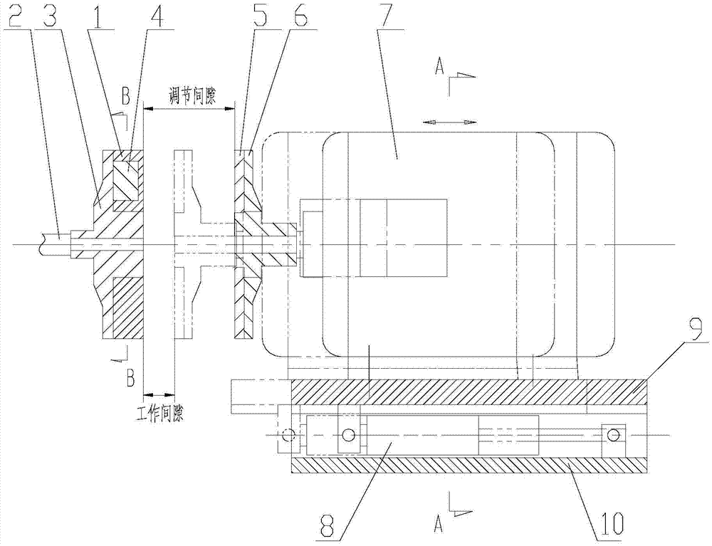
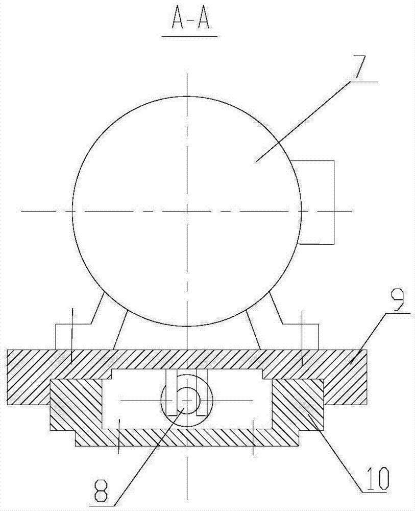
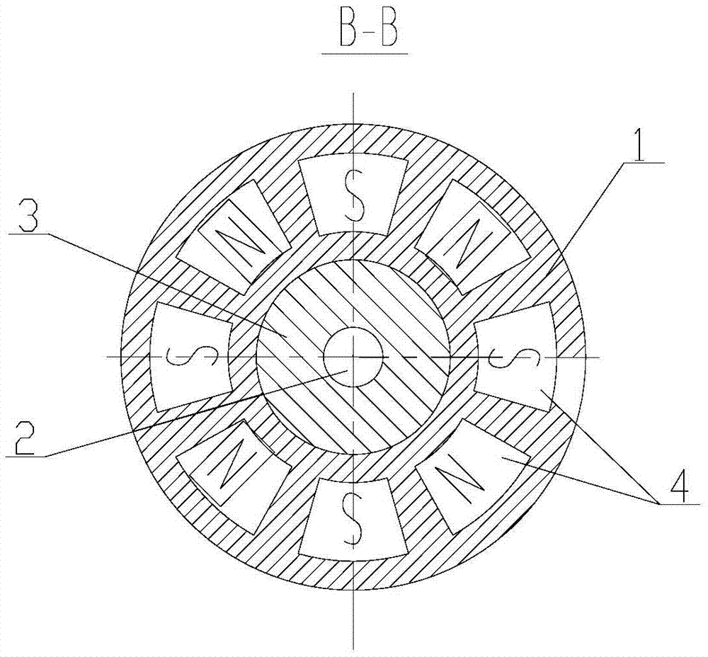
[0026] See Figure 1-Figure 3 , is a structural schematic diagram of the magnetic sensor device of the present invention, a magnetic transmission device with coupling, clutch and speed regulation functions of the present invention, including a permanent magnet eddy current coupling, an axial gap adjustment device and a control device, the The permanent magnet eddy current coupling consists of a copper disc 5 set on the shaft end of the motor and an aluminum disc 1 set on the load shaft end. The copper disc 5 and the aluminum disc 1 are arranged in parallel with a gap in the middle, and the aluminum disc 1 is equipped with a permanent magnet 4 The axial gap adjustment device is composed of an upper slide table 9, a slide table 10 and an electric / electro-hydraulic push rod 8. The table 10 is connected with the upper slide table 9, and the motor 7 i...


PUM


Abstract

The invention relates to a magnetic transmission device having coupling, separation and reunion and speed regulation functions and a mounting method thereof. The magnetic transmission device comprises a permanent magnet eddy-current coupling, an axial gap adjusting device and a control device, wherein the permanent magnet eddy-current coupling consists of a copper disc which sleeves a motor shaft end and an aluminum disc which sleeves a loading shaft end; the copper disc and the aluminum disc are arranged in parallel with a gap being left between the copper disc and the aluminum disc; permanent magnets are arranged in the aluminum disc; the axial gap adjusting device consists of an upper sliding table, a lower sliding table and an electric/electric-hydraulic push rod; a motor is fixed on the upper sliding table, and can be driven to move together with the upper sliding table along an axial direction by the electric/electric-hydraulic push rod; the control device consists of a speed sensor and an external controller arranged on a loading shaft; and the speed sensor is connected with a driving device of the electric/electric-hydraulic push rod through the controller. Through active adjustment of an axial gap between two sensing elements on the motor shaft and the loading shaft, the coupling has the functions of a coupler, a clutch and a speed regulator at the same time.

Description

technical field [0001] The invention relates to a transmission device, in particular to a magnetic transmission device with coupling, clutch and speed regulation functions and an installation method thereof. Background technique [0002] When the existing motor starts to drive under high load, because the starting current is too large, it will generate a large instantaneous current to the grid and the motor, which will easily cause the motor to overheat and cause electrical equipment failure. At present, the best solution is to use frequency conversion speed regulation control to solve the problem of motor overheating and damage, but there are the following problems in the operation process: 1) The structure of the inverter equipment is complex, and it has high requirements on the site environment, which must be cleaned and ventilated Work in a good environment; 2) The frequency converter will generate harmonic interference to the frequency of the grid during frequency conve...

Claims


Application Information

Patent Timeline
Patent Type & Authority Applications(China)
IPC IPC(8): H02K49/10H02K49/04H02K7/10
CPCH02K49/108H02K7/10H02K49/046
Inventor 安振刚张永学
Owner LIAONING MINGDE MAGNETIC POWER TECH CO LTD
Why Eureka
Try Eureka