
A steel ingot turning machine

A steel ingot and spherical roller bearing technology, applied in the direction of workpiece manipulation, etc., can solve the problems of small wheels (rollers are easy to deviate or get stuck, poor stability and startability, affecting the normal operation of the turntable, etc.) The effect of balanced force and improved service life

Inactive Publication Date: 2017-07-14
SICHUAN UNIV
View PDF6 Cites 0 Cited by
  • Summary
  • Abstract
  • Description
  • Claims
  • Application Information

AI Technical Summary

Problems solved by technology

[0003] Regarding the steel ingot turning machine, a kind of "steel ingot turning automatic turntable" is disclosed in the journal "Steel" (No. 3, 1964, P52-53). According to the disclosed content, this kind of steel ingot turning automatic turntable has the following problems: (1 ) Due to the use of worm gear and worm transmission pair, the system is not uniformly stressed, and the worm gear will move up and down with the rotation of the main shaft, resulting in poor stability and startability
(2) Because the circular track is a concave track, it is easy to deposit debris, which causes the small wheel (roller) to easily deviate or get stuck, affecting the normal operation of the turntable

Method used


Image

  • A steel ingot turning machine
  • A steel ingot turning machine
  • A steel ingot turning machine

Examples


Embodiment Construction

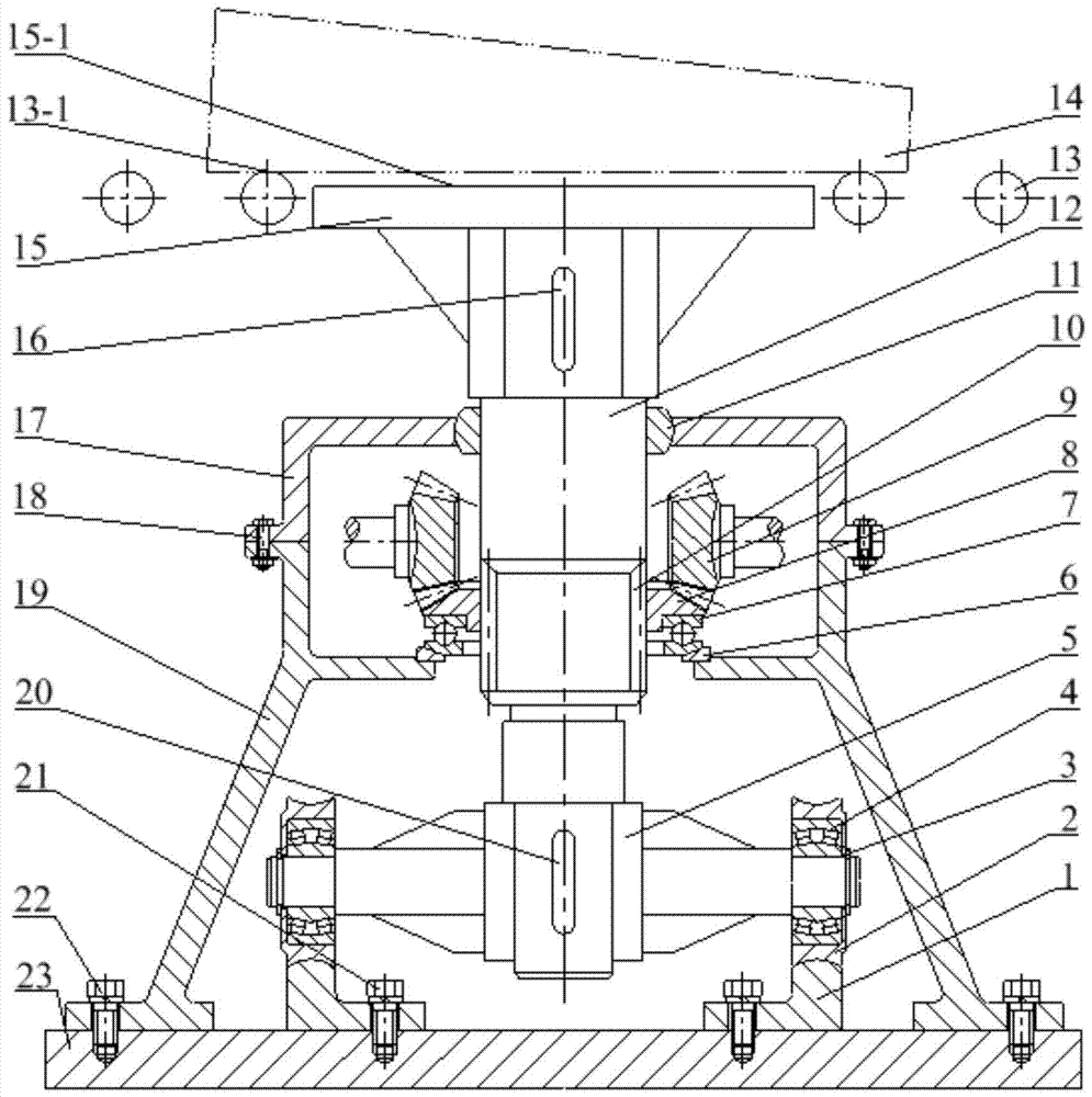
[0028] The structure and usage of the steel ingot turning machine according to the present invention will be further described below through examples and in conjunction with the accompanying drawings.

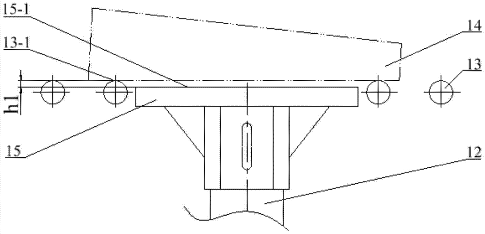
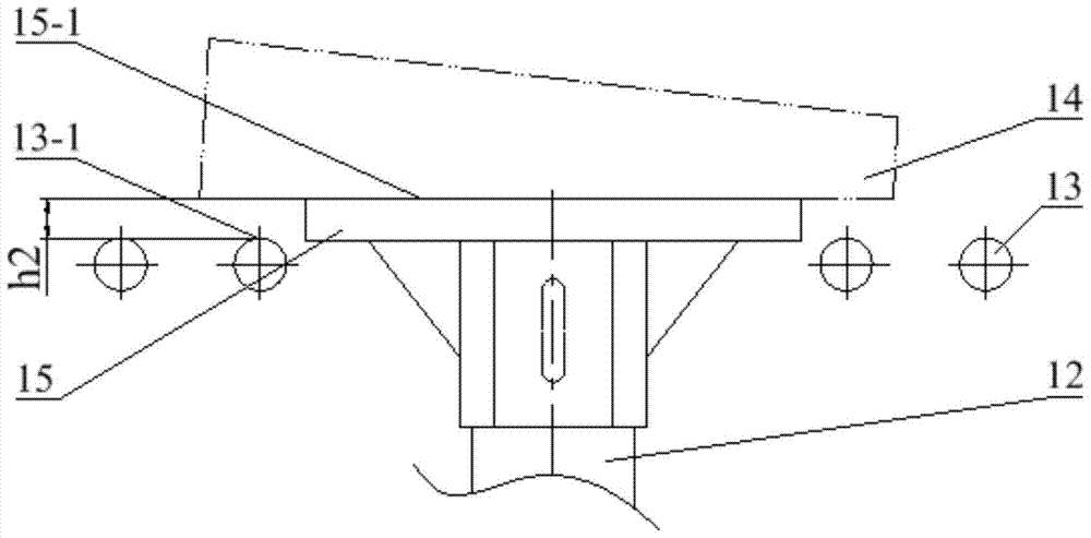
[0029] In this embodiment, the structure of the steel ingot turning machine is as follows: figure 1 As shown, it includes base 23, track body 1, sheave 2, locking ring 3, spherical roller bearing 4, connecting frame 5, main shaft 12, driving bevel gear 9, driven bevel gear 8, transmission shaft 25, spherical Seat 6, thrust ball bearing 7, motor 24, self-aligning sliding bearing 11, tray 15, roller table 13, support cover 19 and cover 17.

[0030] The orbital body such as Figure 4 , Figure 5 , Figure 6 , Figure 7As shown, it is composed of a cylindrical body 1-1 and a mounting lug 1-2 provided at the lower end of the inner wall of the cylindrical body, the lower end surface 1-1-3 of the cylindrical body is a plane, and the upper end surface is a convex arc surface, The ...


PUM


Abstract

The invention discloses a steel ingot reversing machine. The steel ingot reversing machine comprises a base, a rail body, groove wheels, aligning roller bearings, a connecting frame, a main shaft, driving bevel gears, driven bevel gears, transmitting shafts, spherical bases, thrust ball bearings, motors, self-aligning sliding bearings, a tray, roller ways, a supporting cover and a cover cap. The rail body is formed by a cylinder body and installing convex lugs arranged at the lower end of the inner wall of the cylinder body, the upper end face of the cylinder body is a convex arc face, a convex-arc-shaped annular rail is formed on the upper end face of the cylinder body, and the convex-arc-shaped annular rail is composed of two same-shape lower concave sections which are symmetric with respect to the axis of the cylinder body and two same-shape standard sections which are symmetric with respect to the axis of the cylinder body in an alternate manner; and the groove wheels are in circular ring shapes, the outer ring faces of the groove wheels are concave arc faces, and the concave arc faces are matched with the convex arc face on the upper end face of the cylinder body in the rail body. When the steel ingot reversing machine operates, stress of a transmitting system is balanced, the driven bevel gears can not shift vertically along with rotation of the main shaft, and jamming and off tracking of the groove wheels can be avoided.

Description

technical field [0001] The invention belongs to the field of steel rolling equipment, in particular to a steel ingot turning machine used in rolling steel. Background technique [0002] In the steel rolling workshop where steel ingots are used as raw materials, in order to facilitate the pushing of steel ingots, the steel ingots are placed alternately in the heating furnace. During rolling, in order to facilitate feeding the steel ingot into the rolling mill, it is necessary to place the small end of the steel ingot facing the rolling mill. Therefore, a steel ingot turning machine needs to be set between the heating furnace and the rolling mill. [0003] Regarding the steel ingot turning machine, a kind of "steel ingot turning automatic turntable" is disclosed in the journal "Steel" (No. 3, 1964, P52-53). According to the disclosed content, this kind of steel ingot turning automatic turntable has the following problems: (1 ) Due to the use of worm gear and worm transmissio...

Claims


Application Information

Patent Timeline
Patent Type & Authority Patents(China)
IPC IPC(8): B21B39/20
CPCB21B39/20
Inventor 李文强唐忠陶冶李彦
Owner SICHUAN UNIV
Learn More