
Method for ensuring reliability of rotary ultrasonic detection of round rod

A rotating ultrasonic and ultrasonic testing technology, which is applied to the analysis of solids using sound waves/ultrasonic waves/infrasonic waves, the use of sound waves/ultrasonic waves/infrasonic waves for material analysis, and measuring devices, etc., can solve the problem of affecting the reliability of automatic rotating ultrasonic detection of round rods and damage equipment Problems such as functional accuracy and normal operating life, the rotating water layer cannot stably contact the surface of the round bar, etc., to reduce false alarm re-inspection and offline confirmation work, eliminate the phenomenon of equipment jamming, prolong the maintenance time and the normal service life of the equipment

Pending Publication Date: 2021-10-26
BAOSTEEL SPECIAL STEEL SHAOGUAN CO LTD
View PDF6 Cites 1 Cited by
  • Summary
  • Abstract
  • Description
  • Claims
  • Application Information

AI Technical Summary

Problems solved by technology

In the actual inspection, due to the influence of the bending degree and shape of the real round rod and the operation accuracy of the equipment, it is usually difficult to calibrate the guide sleeves according to the guide sleeve clearance of the acceptance test.
When matching the inner diameter of the guide sleeve according to the actual situation, the following problems occurred: when the inner diameter of the guide sleeve is not large enough, the surface of the jammed steel, impact equipment and round rods are frequently scratched. Among them, the jammed steel and impact equipment will directly damage the function of the equipment Accuracy and normal operating life; when the inner diameter of the guide sleeve is too large, the rotating water layer in the rotating chamber cannot stably contact the surface of the round rod, and the phenomenon of false detection of artificial damage at the head and tail or false alarms of non-defects frequently occurs during the calibration of the sample rod. During the calibration of the sample rod, the problem of missed detection and false alarm is more serious due to the swing of the head and tail section; when using a guide sleeve with a suitable inner diameter, the inner diameter of the guide sleeve is prone to be enlarged due to uneven wear during the detection process, and then the inner diameter of the guide sleeve is too large. The phenomenon of missed detection and false positives, such as frequent measurement and replacement of worn guide sleeves, also increases the detection cost
The above problems become more frequent and serious as the detection speed increases. Correspondingly, the problems that occur during the sample rod calibration will also occur in the physical detection, which seriously affects the reliability of the automatic rotating ultrasonic detection of the round rod. In order to ensure the accuracy of the detection However, it can only confirm the off-line manual ultrasonic detection of the alarm part of the round bar detection, which increases the extra work and affects the operation efficiency. However, the missed detection part cannot be confirmed, and the risk of missed detection cannot be overcome

Method used


Image

  • Method for ensuring reliability of rotary ultrasonic detection of round rod
  • Method for ensuring reliability of rotary ultrasonic detection of round rod
  • Method for ensuring reliability of rotary ultrasonic detection of round rod

Examples


Embodiment Construction

[0031] The present invention will be described in detail below in conjunction with the accompanying drawings and embodiments.

[0032] It is worth noting that the orientation words such as "up" and "down" involved in this article are all determined relative to the perspective of the drawings, and are only for the convenience of description, and cannot be understood as limitations on the technical solution.

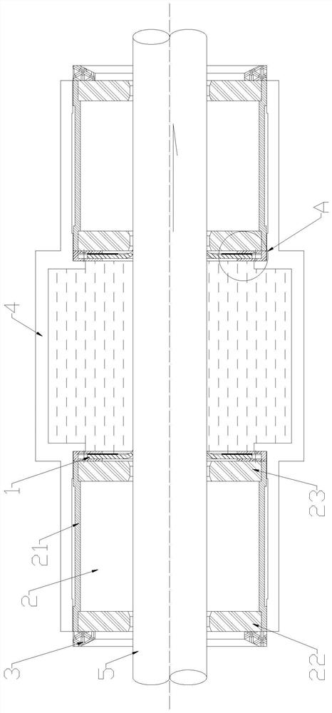
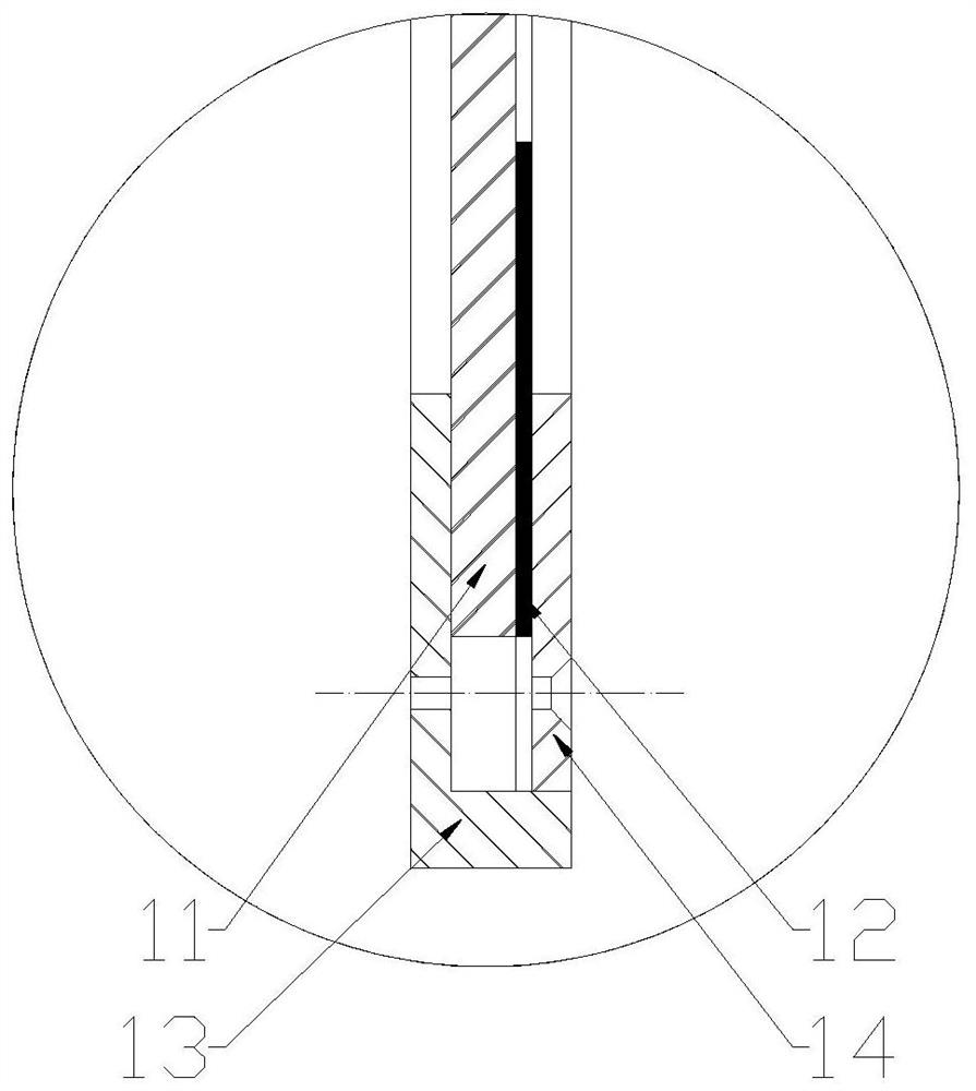
[0033] In the existing ultrasonic testing equipment for the detection of the round bar 5, the wiper device 1 is located on the outermost side of the ultrasonic testing equipment, the guide device 2 is located between the wiper device 1 and the rotating cavity 4, and then the outermost side of the wiper device 1 Fix with the pressure ring 3, so that the wiper device 1 and the guide device 2 are fixed in the cylinder on both sides of the ultrasonic testing equipment. When the round rod 5 passes through the ultrasonic testing equipment, it first enters the guide device on the ...


PUM


Abstract

The invention relates to a method for ensuring the reliability of rotary ultrasonic detection of a round bar, which comprises the following steps: a mounting step: respectively mounting water scraping devices in cylinders on two sides of ultrasonic detection equipment, and respectively positioning the two water scraping devices on two sides of a rotary cavity in the middle of the ultrasonic detection equipment; installing guiding devices in the cylinder bodies on the two sides, fixing the water scraping devices on the same side to the outside of the end opening of the rotating cavity through the guiding devices, and fixing the guiding devices into the cylinder bodies through pressing rings; The detection method comprises the following steps: leading in a round rod from a barrel on one side of the ultrasonic detection equipment at a constant speed, sequentially penetrating through a leading-in side guide device and a water scraping device to enter a rotating cavity to be subjected to spiral scanning detection, then leading out the round rod from a barrel on the other side, sequentially penetrating through a leading-out side water scraping device and a guide device to leave the ultrasonic detection equipment, and when penetrating through the water scraping devices, the round bars are in tight elastic contact with the water scraping devices on the two sides respectively. Rotation ultrasonic detection reliability of the head section and the tail section of the round rod is ensured, and meanwhile the phenomena that the round rod collides with equipment, clamps steel and scratches the surface in the detection process are avoided.

Description

technical field [0001] The invention relates to the technical field of ultrasonic detection of round rods, more specifically, it relates to a method for ensuring the reliability of ultrasonic detection of round rod rotation. Background technique [0002] In the production of special round steel, ex-factory quality inspection is an indispensable procedure. Rotating ultrasonic automatic inspection is an efficient inspection method for the internal quality of round bars. The inspection process is that the ultrasonic probe rotates around the round bar while the round bar passes through the equipment. And continuously transmit and receive ultrasonic waves to realize the spiral scanning of the round rod. The coupling water is filled between the ultrasonic probe and the round rod, and the ultrasonic wave emitted by the ultrasonic probe is incident into the round rod through the coupling water, and the instrument judges the internal quality of the round rod according to the ultrason...

Claims


Application Information

Patent Timeline
Patent Type & Authority Applications(China)
IPC IPC(8): G01N29/04G01N29/22G01N29/275G01N29/28
CPCG01N29/043G01N29/275G01N29/28G01N29/22G01N29/225G01N2291/0234G01N2291/0289G01N2291/2626G01N2291/2634
Inventor 胡柏上周文军刘栋麻国晓张浩高伟石秋生邹毅鸿麦海源
Owner BAOSTEEL SPECIAL STEEL SHAOGUAN CO LTD
Learn More