High-speed electric main shaft device where ultra-precise angular contact ball and cylindrical roller bearings are used

A technology for cylindrical roller bearings and high-speed motorized spindles, which is used in maintenance and safety accessories, large fixed members, metal processing machinery parts, etc., which can solve the difficulty of test bearing disassembly and assembly, the inability to accurately lubricate a single specific bearing, and the inability to reflect the running performance. and other problems, to achieve the effect of accurate quantitative lubrication, convenient, good rigidity and high reliability

Inactive Publication Date: 2016-04-06
XI AN JIAOTONG UNIV
View PDF6 Cites 8 Cited by
  • Summary
  • Abstract
  • Description
  • Claims
  • Application Information

AI Technical Summary

Problems solved by technology

First of all, the existing rolling bearing experimental device is mainly for the installation and measurement of a single bearing, and the rolling bearing in the electric spindle is greatly affected by the electric spindle system during operation. For the rolling bearing in the non-working environment and operating conditions None of these researches can reflect the real operating performance of this type of bearing under actual worki

Method used


Image

  • High-speed electric main shaft device where ultra-precise angular contact ball and cylindrical roller bearings are used
  • High-speed electric main shaft device where ultra-precise angular contact ball and cylindrical roller bearings are used
  • High-speed electric main shaft device where ultra-precise angular contact ball and cylindrical roller bearings are used

Examples


Embodiment Construction

[0021] The technical solution of the present invention will be described in detail below in conjunction with the accompanying drawings.

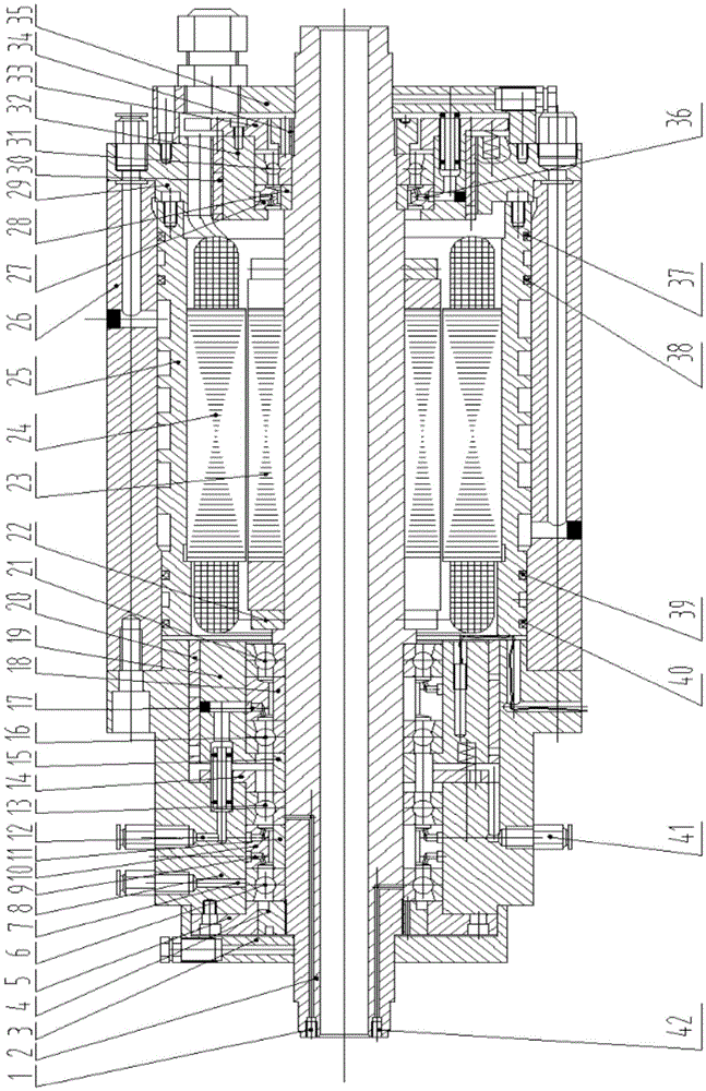
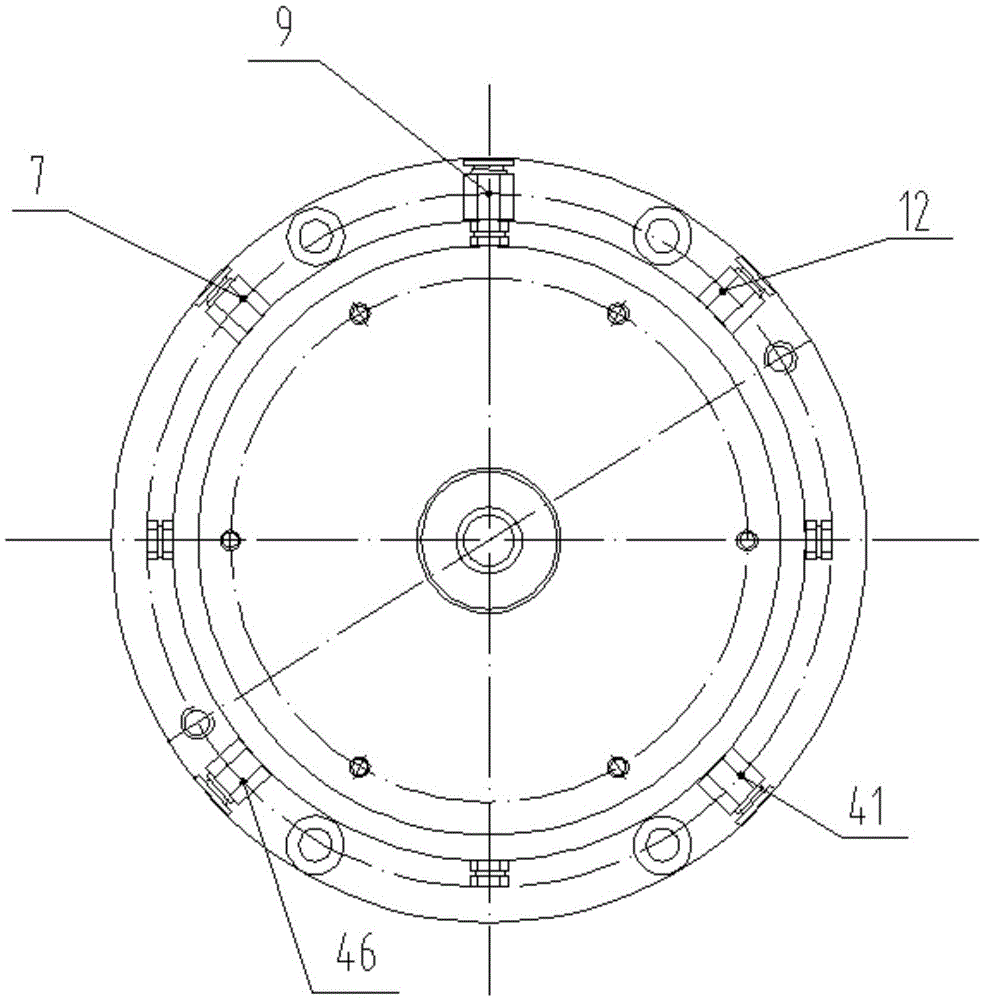
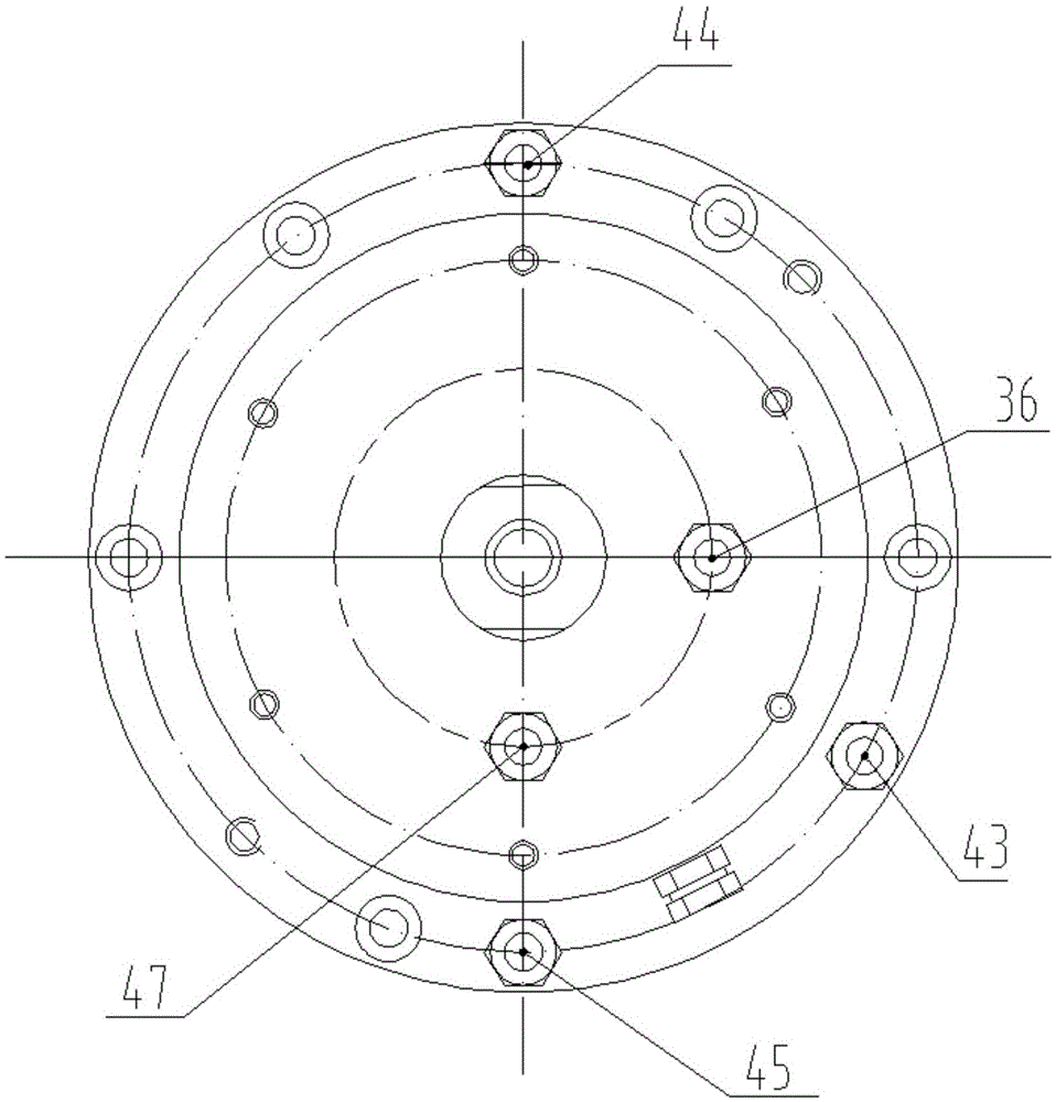
[0022] refer to figure 1 , figure 2 and image 3 , a high-speed electric spindle experimental device supported by angular contact balls and cylindrical roller bearings, including a housing 26, the housing 26 is used as the motor base, the cooling water jacket 25 is interference-fitted in the housing 26, and the motor stator 24 is interference-fitted Cooperate installed in the cooling water jacket 25, the motor rotor 23 and balance ring 22 are installed on the rotating shaft 2 with interference fit, the motor rotor 23 corresponds to the motor stator 24; the rear end of the rotating shaft 2 is provided with a single row cylindrical roller bearing 31, single row The front side of the cylindrical roller bearing 31 is positioned through the contact between the rear inner spacer 28 and the steps of the rotor 2, and the rear outer spacer 27 is i...


PUM


Abstract

The invention discloses a high-speed electric main shaft experimental device supported by an angular contact ball and cylindrical roller bearings. A single column of cylindrical roller bearings with conical holes are arranged at the rear end of a rotating shaft. A first front supporting bearing, a second front supporting bearing, a third front supporting bearing and a fourth front supporting bearing are arranged at the front end of the rotating shaft. The first front supporting bearing and the second front supporting bearing are connected in series to form a group. The third front supporting bearing and the fourth front supporting bearing are connected in series to form a group. The two groups are arranged in a back-to-back manner. A gap between the two groups is supplemented by a shaft shoulder sleeve, and the two groups are separated through a front spring baffle. The first front supporting bearing and the second front supporting bearing are testing bearings. The third front supporting bearing and the fourth front supporting bearing are auxiliary supporting bearings. The actual work environment needed for monitoring and researching a rolling bearing in the high-speed electric main shaft device is achieved, the structure supporting rigidity is good, precise and quantitative lubrication is achieved, the testing bearings can be conveniently replaced, and precision stability of an electric main shaft is guaranteed during long-time running.

Description

technical field [0001] The invention belongs to the technical field of high-speed electric spindles for machine tools, and in particular relates to a high-speed electric spindle device using ultra-precision angular contact balls and cylindrical roller bearings. Background technique [0002] The high-speed electric spindle is the key to high-speed cutting, and it is usually directly driven by a variable frequency motor. The built-in electric spindle integrates the motor rotor and the electric spindle. The rotor of the motor is also used as the electric spindle of the machine tool, and the motor base is also the shell of the electric spindle unit, thus realizing the "zero transmission" between the motor and the electric spindle of the machine tool. It overcomes the shortcomings of the mechanical electric spindle system with traditional transmission methods such as additional moment of inertia, large vibration and noise, and is easy to slip. Dynamic balance makes it easier for...

Claims


Application Information

Patent Timeline
IPC IPC(8): B23B19/02B23Q11/12
CPCB23Q1/70B23Q11/123
Inventor 徐华夏平陈晓雷
Owner XI AN JIAOTONG UNIV
Why Eureka
Try Eureka