Laser cutting device

A technology of laser cutting and laser transmitter, which is applied in the direction of laser welding equipment, welding equipment, metal processing equipment, etc., can solve the problems of inaccurate cutting of pole pieces, prone to deflection, easy to produce pits, burrs, etc., and achieve production The effect of improving efficiency, improving alignment accuracy, and reducing wrinkles

Active Publication Date: 2016-04-06
INST OF IND TECH GUANGZHOU & CHINESE ACADEMY OF SCI
View PDF6 Cites 16 Cited by
  • Summary
  • Abstract
  • Description
  • Claims
  • Application Information

AI Technical Summary

Problems solved by technology

[0002] Existing die-cutting of battery pole pieces adopts the die-cutting process, but the die-cutting process has the following defects: First, in order to ensure the cutting quality of battery pole pieces, the knife dies often need to be repaired, resulting in higher processing costs for battery pole pieces ;Secondly, the blanking process of the battery pole piece is a static process, and the processing efficiency is low, and the battery pole piece material belt is prone to deflection during the transmission process, resulting in the undesirable phenomenon of inaccurate cutting of the pole piece; in addition, using a knife During the die-to-electrode punching process, burrs are likely to occur on the cutting part of the battery pole piece
After the fly-cutting action of the battery pole strip is completed, since the front end of the battery pole has no traction, it is easy to cause the battery pole strip to be wrinkled during transmission
Secondly, the support plate supporting the battery pole piece on the cutting station is affected by laser irradiation for a long time, which is prone to pits and burrs, and even the aluminum foil is welded to the support plate during the fly-cutting action of the pole piece, which causes the strip material to be damaged during transmission. Wrinkles occur, which seriously hinders the processing and production of battery pole pieces

Method used


Image

  • Laser cutting device
  • Laser cutting device
  • Laser cutting device

Examples


Embodiment Construction

[0032] Embodiments of the present invention are described in detail below:

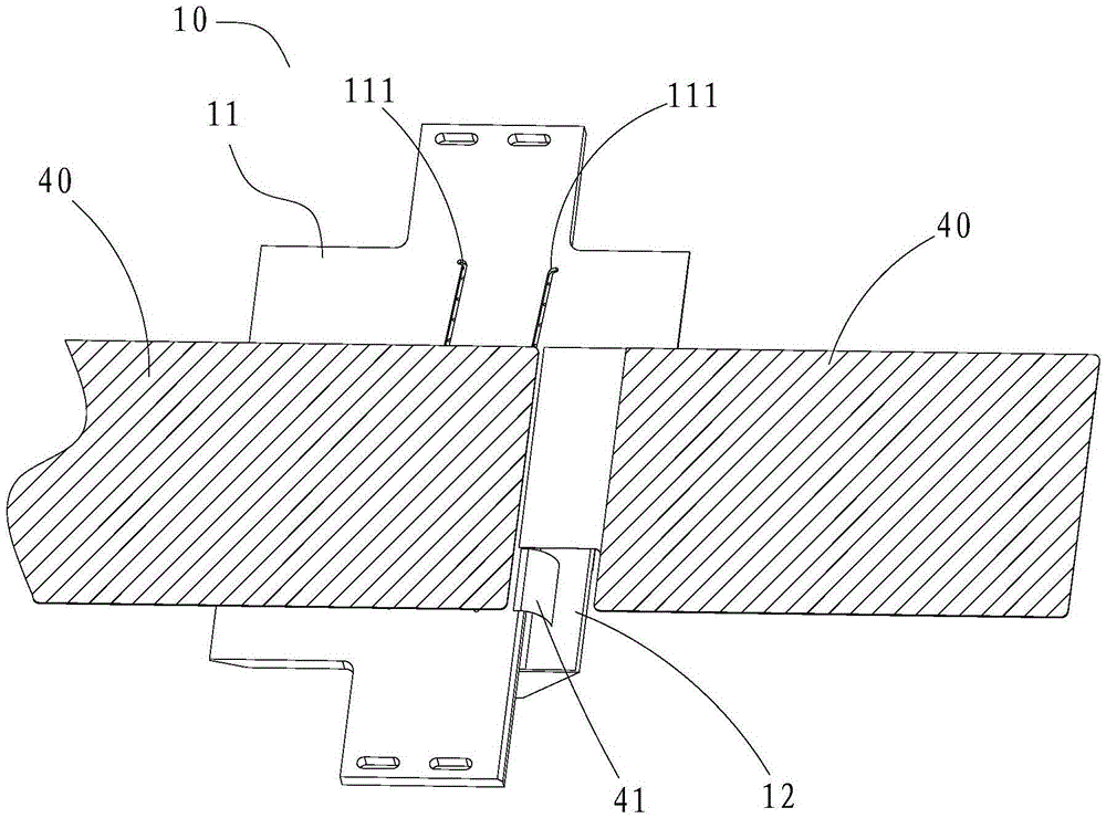
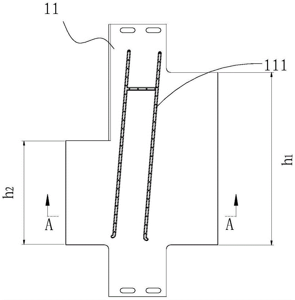
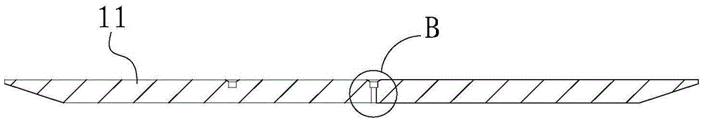
[0033] Such as figure 1As shown, the laser cutting device of the present invention includes a laser cutting mechanism 10 . The laser cutting mechanism 10 includes a support plate 11 for carrying the battery pole piece 40 , and a laser emitter (not shown in the figure) opposite to the support plate 11 . The laser emitter is used for cutting the battery pole piece 40 , and the support plate 11 is provided with a groove 111 on the side opposite to the laser emitter. The main purpose of the groove 111 is to make the support plate 11 avoid the laser beam emitted by the laser emitter, so as to prevent the laser beam from damaging the support plate 11 when cutting the battery pole piece 40 . And the shape of the groove 111 is set according to the cutting shape of the battery pole piece 40, for example, the shape of the groove 111 can be set to H type, T type or W type, which is convenient for the laser tra...


PUM


Abstract

The invention discloses a laser cutting device. The laser cutting device comprises a laser cutting mechanism. The laser cutting mechanism comprises a supporting plate used for bearing a battery pole piece, and a laser transmitter opposite to the supporting plate. The laser transmitter is used for cutting the battery pole piece, and the face, opposite to the laser transmitter, of the supporting plate is provided with a groove. According to the laser cutting device, after a battery pole piece strip is conveyed onto the supporting plate, the laser transmitter transmits lasers towards the groove so as to cut the battery pole piece strip at the position corresponding to that of the groove; in the process of transmitting the lasers to cut the battery pole piece, the groove can avoid a fly-cutting optical path of the lasers, then the bad phenomena of pits, burrs and the like caused when the cutting position of the supporting plate is influenced by the lasers for a long time can be avoided, the bad phenomenon that aluminum foil is welded to the supporting plate in pole piece fly-cutting motion is also avoided, the phenomenon that the strip wrinkles when conveyed can be reduced, and therefore the production efficiency of the battery pole piece is greatly improved.

Description

technical field [0001] The invention relates to the technical field of cutting battery pole pieces, in particular to a laser cutting device. Background technique [0002] Existing die-cutting of battery pole pieces adopts the die-cutting process, but the die-cutting process has the following defects: First, in order to ensure the cutting quality of battery pole pieces, the knife dies often need to be repaired, resulting in higher processing costs for battery pole pieces ;Secondly, the blanking process of the battery pole piece is a static process, and the processing efficiency is low, and the battery pole piece material belt is prone to deflection during the transmission process, resulting in the undesirable phenomenon of inaccurate cutting of the pole piece; in addition, using a knife During the die-to-electrode punching process, the cutting part of the battery electrode is prone to burrs. In order to reduce production costs, improve production efficiency, and reduce cutti...

Claims


Application Information

Patent Timeline
Patent Type & Authority Applications(China)
IPC IPC(8): B23K26/38B23K26/70
CPCB23K26/38
Inventor 黄学杰徐腾飞王超邓永丽周方方
Owner INST OF IND TECH GUANGZHOU & CHINESE ACADEMY OF SCI
Why Eureka
Try Eureka