Welding positioning mechanism for lower cover and middle cover of pneumatic type air inlet manifold

An intake manifold, welding positioning technology, applied in welding equipment, auxiliary welding equipment, welding/cutting auxiliary equipment, etc., can solve the problem of long positioning operation time, inconsistent production, poor positioning reliability, etc. problem, to achieve the effect of simple structure, small footprint, easy processing and production

Active Publication Date: 2016-04-06
CHONGQING ANBIXIN AUTOMOBILE INTAKE SYST CO LTD
View PDF5 Cites 1 Cited by
  • Summary
  • Abstract
  • Description
  • Claims
  • Application Information

AI Technical Summary

Problems solved by technology

The existing welding positioning device not only has a complex structure, takes up a lot of space, and is expensive, but also takes a long time for positioning operations, which will affect the efficiency of welding
In addition, the reliability of positioning is not good, and relative movement may occur between the lower cover and the middle cover during the welding process, which will reduce the welding quality and fail to meet the requirements of consistent production

Method used


Image

  • Welding positioning mechanism for lower cover and middle cover of pneumatic type air inlet manifold
  • Welding positioning mechanism for lower cover and middle cover of pneumatic type air inlet manifold

Examples


Embodiment Construction

[0014] Below in conjunction with accompanying drawing and embodiment the present invention will be further described:

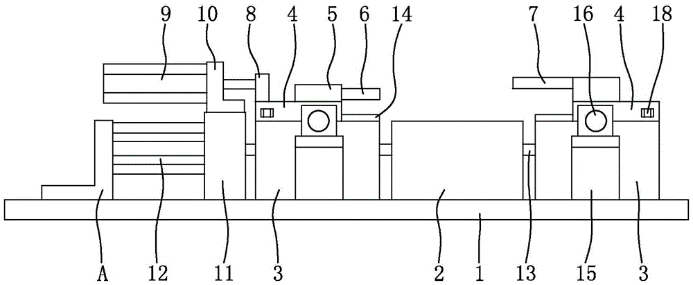
[0015] Such as figure 1 As shown, the bottom plate 1 is a rectangular steel flat plate structure, and the mold base 2 is installed on the base plate 1. The bottom of the mold base 2 is fixed to the base plate 1, and the shape of the top of the mold base 2 is adapted to the lower cover of the intake manifold. The left and right sides of mold base 2 are provided with fixed seat 3 symmetrically, and fixed seat 3 is flat-bottomed " U " shape, and the bottom surface of fixed seat 3 is supported on the base plate 1, and fixed seat 3 is fixedly connected together with base plate 1 by bolt. Two mutually parallel guide rails 14 are installed on the top of each fixed seat 3, and the fixed seat 3 is supported with a slide plate 4, and the slide plate 4 slides with the guide rail 14 at the top of the corresponding fixed seat 3 through the chute at its bottom.

[0016] S...


PUM


Abstract

The invention discloses a welding positioning mechanism for a lower cover and a middle cover of a pneumatic type air inlet manifold. Fixed bases are in a flat-bottom U shape. Sliding plates are arranged on the tops of the fixed bases. Each sliding plate is provided with an adapter coupling block. A pressing plate is fixed to the right end of the left adapter coupling block. A base plate is fixed to the left end of the right adapter coupling block. A locking block is installed on the left sliding plate. The locking block is connected with a piston rod of a push-pull air cylinder. The output end of a rotary air cylinder is connected with a lead screw. The lead screw is sleeved with a nut bed. The nut bed is fixed to the bottom of the right sliding plate. The front side and the right side of each fixed base are symmetrically provided with clamping air cylinders. Piston rods of the clamping air cylinders are connected with clamping blocks. The clamping blocks are provided with positioning grooves. Positioning blocks matched with the positioning grooves are fixed to the sliding plates. The welding positioning mechanism is ingenious in concept, novel in design, easy to implement, low in cost, flexible and rapid in operation, high in automation degree, capable of effectively improving the welding efficiency, good in positioning reliability and capable of ensuring the welding quality.

Description

technical field [0001] The invention relates to a welding positioning mechanism for a lower cover and a middle cover of a pneumatic intake manifold. Background technique [0002] At present, the lower cover and the middle cover of the automobile intake manifold are usually fixed together by vibration friction welding, and special tooling is required for positioning during welding. The existing welding positioning device not only has a complex structure, takes up a large space, and has high cost, but also takes a long time for the positioning operation, which will affect the welding efficiency. In addition, the reliability of positioning is not good, and relative movement may occur between the lower cover and the middle cover during the welding process, which will reduce the welding quality and fail to meet the requirements of consistent production. Contents of the invention [0003] The technical problem to be solved by the present invention is to provide a pneumatic inta...

Claims


Application Information

Patent Timeline
Patent Type & Authority Applications(China)
IPC IPC(8): B23K37/04
CPCB23K37/0443
Inventor 李科志
Owner CHONGQING ANBIXIN AUTOMOBILE INTAKE SYST CO LTD
Why Eureka
Try Eureka