
Combined machining device special for shifting fork

A combined processing and equipment technology, which is applied in the direction of mechanical equipment, other manufacturing equipment/tools, manufacturing tools, etc., can solve the problems of symmetry, parallelism, and positional tolerances that are difficult to guarantee, large cumulative positioning tolerances, and low production efficiency. , to achieve the effect of reducing tolerance accumulation, satisfying processing, and short processing cycle

Inactive Publication Date: 2016-04-06
湖北华阳汽车变速系统股份有限公司
View PDF11 Cites 5 Cited by
  • Summary
  • Abstract
  • Description
  • Claims
  • Application Information

AI Technical Summary

Problems solved by technology

The current machining process of the shift fork is: pulling the inner hole-milling the gear-milling the flat part of the shift fork-drilling. Among them, milling the gear, milling the flat part of the shift fork, and drilling are carried out on separate processing equipment. Three times of clamping, three sets of tooling, and three operators, due to multiple clamping, the cumulative positioning tolerance is large, the symmetry, parallelism and position tolerance are difficult to guarantee, and the production efficiency is low and the processing cost is high

Method used


Image

  • Combined machining device special for shifting fork
  • Combined machining device special for shifting fork
  • Combined machining device special for shifting fork

Examples


Embodiment Construction

[0015] Further describe the present invention below in conjunction with accompanying drawing as follows.

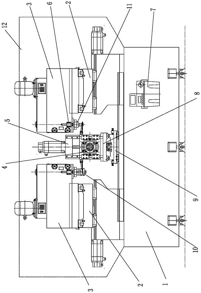
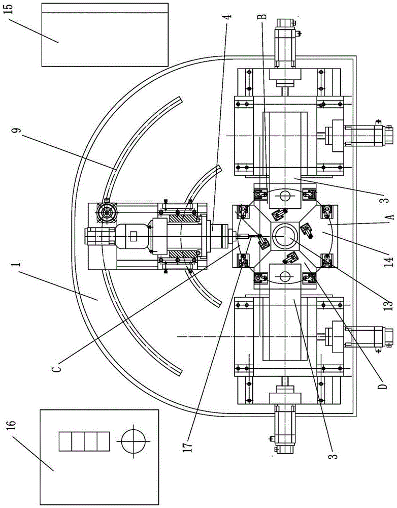
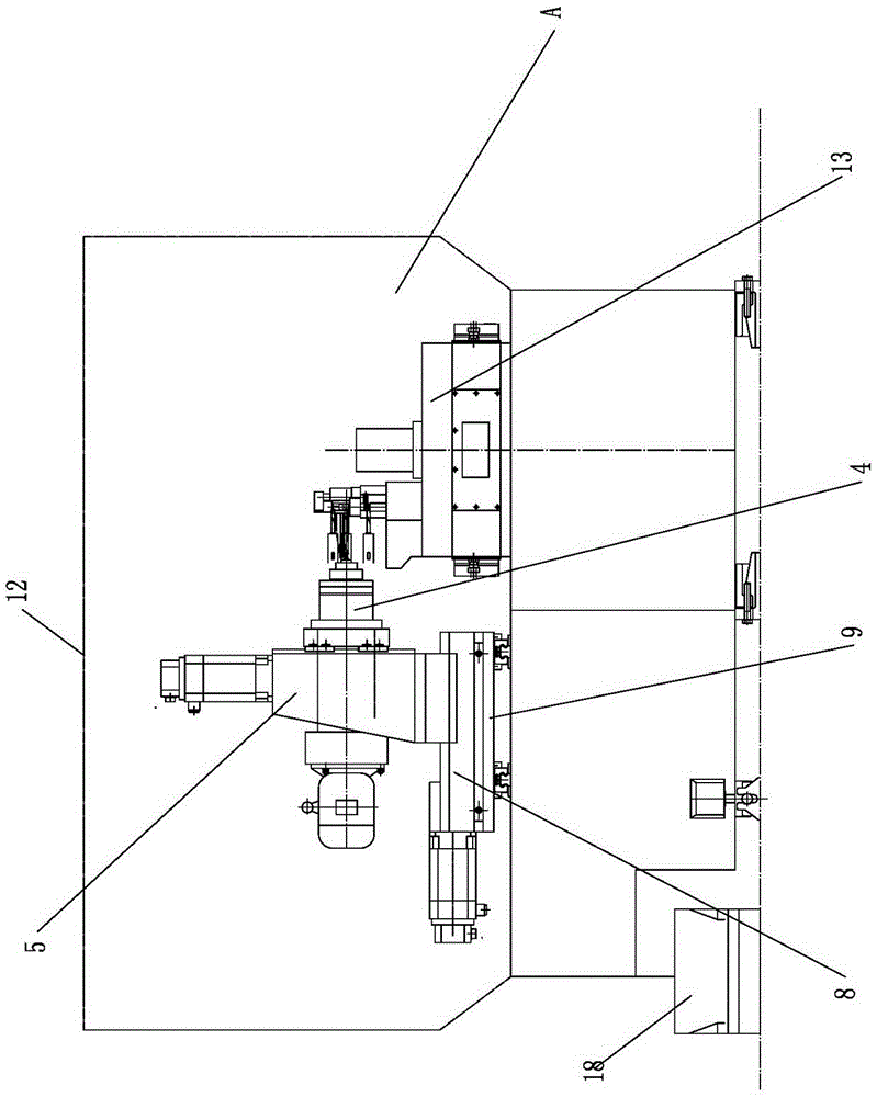
[0016] To make the figure clear, figure 1 The hydraulic rotary table and hydraulic fixture are omitted; image 3 The vertical milling power head and CNC cross slide table on both sides are omitted; figure 2 The hydraulic system and electrical control system in the figure 1 and figure 2 is omitted.

[0017] like figure 1 , figure 2 and image 3 As shown, the special combined processing equipment for shift fork includes integral bed 1, a set of hydraulic rotary table 13, two sets of CNC cross slides 2, two sets of vertical milling power heads 3, a set of boring power heads 4, four Set of hydraulic clamps 14, electrical control system 15, hydraulic system 16, centralized lubrication device 7, cooling chip removal device 18, hydraulic rotary table 13 is fixed in the middle of the overall bed 1, and two sets of CNC cross slides 2 are respectively installed on the On...


PUM


Abstract

The invention provides a combined machining device special for a shifting fork. The combined machining device special for the shifting fork comprises a complete lathe body, a hydraulic rotating workbench, two numerical control cross sliding tables, two vertical milling power heads, a boring power head, four hydraulic clamps, an electrical control system, a hydraulic system, a concentrated lubricating device and a cooling and chip removing device. A clamping station is arranged on the front side of the hydraulic rotating workbench; an open gear milling station and a shifting fork flat part milling station are arranged on the corresponding side faces of the two vertical milling power heads fixed to the numerical control cross sliding tables; and a hole drilling station is correspondingly arranged behind the boring power head, and therefore four stations are formed. Four parts can be clamped by the combined machining device special for the shifting fork at a time, the three procedures of milling an opening gear, milling a shifting fork flat part and drilling a hole can be completed through one time of clamping, clamping of the parts is not affected in the machining process, and the deformation quantity of the shifting fork is eliminated through hydraulic pressing; and the machining tact is short, and production efficiency is greatly improved.

Description

technical field [0001] The invention belongs to the processing equipment of the components of the transmission control mechanism, in particular to the special combined processing equipment for the shift fork. Background technique [0002] The shift fork is a part of the speed change control mechanism, which is used in automobile gearboxes or other mechanical equipment that needs to change speed. The current machining process of the shift fork is: pulling the inner hole-milling the gear-milling the flat part of the shift fork-drilling. Among them, milling the gear, milling the flat part of the shift fork, and drilling are carried out on separate processing equipment. Three times of clamping, three sets of tooling, and three operators, due to multiple clamping, the cumulative positioning tolerance is large, the symmetry, parallelism and position tolerance are difficult to guarantee, and the production efficiency is low and the processing cost is high. Contents of the inventi...

Claims


Application Information

Patent Timeline
Patent Type & Authority Applications(China)
IPC IPC(8): B23P23/02
CPCB23P23/02F16H63/32
Inventor 杨文胜姚世煜刘俊王永意王虎龚高云
Owner 湖北华阳汽车变速系统股份有限公司
Learn More