Lathe center frame and use method thereof

A technology of center frame and lathe, which is applied in the direction of large fixed members, metal processing machinery parts, metal processing equipment, etc. It can solve the problems of complex process, affecting the mechanical performance of parts, affecting the appearance, etc., so as to achieve convenient use and improve processing centering Accuracy, the effect of improving work efficiency

Inactive Publication Date: 2016-04-06
THE THIRD COAL MINE MACHINERY LTD OF ZHANGJIAGANG
View PDF9 Cites 3 Cited by
  • Summary
  • Abstract
  • Description
  • Claims
  • Application Information

AI Technical Summary

Problems solved by technology

The installation method of the above-mentioned center frame and the center frame has complicated procedures, and there is a certain wear and tear on the surface of the positioning reference circle produced by s

Method used


Image

  • Lathe center frame and use method thereof
  • Lathe center frame and use method thereof

Examples


Embodiment Construction

[0024] The present invention will be described in further detail below in conjunction with the accompanying drawings and embodiments.

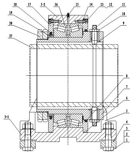
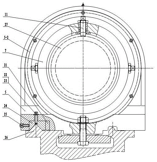
[0025] Such as figure 1 , figure 2 As shown, the present invention includes a stand 5, a bearing 16, an inner sleeve 7 and a workpiece compression screw 11, and the stand 5 includes a base 5-1 and an outer sleeve 5-2 that can be fixed with a lathe guide rail 26 , the outer sleeve 5-2 is fixed on the upper part of the base 5-1, the inner sleeve 7 extends into the middle of the outer sleeve 5-2, and the inner sleeve 7 and the outer sleeve 5-2 rotate through a bearing 16 connected, and the front end of the inner sleeve 7 protrudes from the front end of the outer sleeve 5-2, the wall of the front end of the inner sleeve 7 is radially provided with at least three threaded holes uniformly distributed along the circumference of the wall, The workpiece compression screw 11 is installed in the threaded hole.

[0026] Further, the bearing 16 is a do...


PUM


Abstract

The invention discloses a lathe center frame and a use method thereof and belongs to the technical field of lathe equipment. The lathe center frame comprises a frame base, a bearing, an inner sleeve and compression screws for a machined workpiece, wherein the frame base comprises a base fixed to a lathe guide rail and an outer sleeve; the outer sleeve is fixed to the upper portion of the base; the inner sleeve extends into the middle of the outer sleeve; the inner sleeve and the outer sleeve are rotationally connected through the bearing; the front end of the inner sleeve extends out of the front end face of the outer sleeve; the sleeve wall of the front end of the inner sleeve is provided with at least three threaded holes in the radial direction; the threaded holes are evenly distributed in the circumference of the sleeve wall; the compression screws for the machined workpiece are installed inside the threaded holes. The use method of the lathe center frame comprises the steps that the compression screws are fastened to compress the machined workpiece, circular runout of the machine workpiece is detected through a dial indicator until the circular runout is the minimum, and the compression screws are fastened finally. The lathe center frame is especially suitable for machining thin and long workpieces, the rigidity of the workpieces is increased, deformation is reduced, the machining accuracy is improved, the working procedures are reduced, and the work efficiency is improved.

Description

technical field [0001] The invention relates to the technical field of lathe equipment. Background technique [0002] Hydraulic cylinder barrel is a very important part of hydraulic equipment. There are strict requirements on the roundness, coaxiality and surface roughness of hydraulic cylinder barrel. Therefore, its processing must be strictly controlled. [0003] The cylinder of the hydraulic cylinder needs to be chamfered at 45 degrees before boring, and after boring, it needs to be turned and other processes. Due to the long length of the cylinder, in order to ensure the processing quality and improve the centering accuracy of the cylinder, it is necessary to add a center rack for auxiliary support. The traditional center frame consists of a bottom fixed frame, an upper movable frame and three screw-in jaws. According to the traditional installation process, before installing the center frame, the outer circle of the cylinder where the center frame is installed is first...

Claims


Application Information

Patent Timeline
IPC IPC(8): B23Q1/76
CPCB23Q1/76
Inventor 马晨光侯冬梅王东
Owner THE THIRD COAL MINE MACHINERY LTD OF ZHANGJIAGANG
Why Eureka
Try Eureka