Eureka AIR delivers breakthrough ideas for toughest innovation challenges, trusted by R&D personnel around the world.

Quick rubber tube locating device

A positioning device and fast technology, applied in metal processing and other directions, can solve the problem of inaccurate cutting position, etc., and achieve the effect of simple operation, simple structure and reduced wear

Inactive Publication Date: 2016-04-06
CHONGQING SHENGBO TECH DEV CO LTD
View PDF0 Cites 1 Cited by
  • Summary
  • Abstract
  • Description
  • Claims
  • Application Information

AI Technical Summary

Problems solved by technology

[0004] In order to solve the problem of inaccurate cutting position when the rubber hose is cut and fixed manually, the purpose of the invention is to provide a quick positioning device for rubber hose with simple structure

Method used


Image

  • Quick rubber tube locating device

Examples


Embodiment Construction

[0013] The present invention will be described in further detail below by means of specific embodiments:

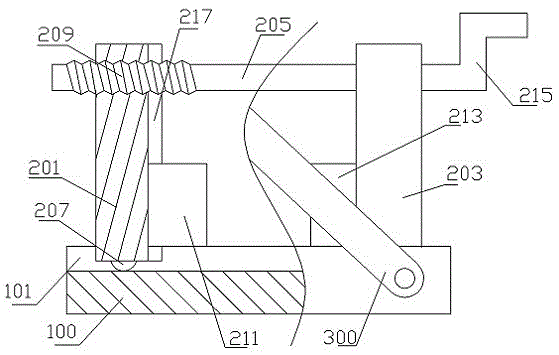
[0014] The reference signs in the accompanying drawings of the description include: machine base 100, chute 101, left slider 201, right slider 203, rotating shaft 205, left pulley 207, left threaded end 209, left clamping block 211, right clamping block 213, handle 215, left chute 217, guillotine 300.

[0015] Such as figure 1 The rubber hose rapid positioning device shown includes a base 100, a guillotine 300 and a positioning mechanism. The base 100 is provided with a chute 101, and the positioning mechanism includes a left slider 201, a right slider 203, a left clamping block 211, and a right clamp. Holding block 213 and rotating shaft 205, the bottom surface of left slide block 201 is provided with left pulley 207, and left pulley 207 offsets with chute 101, and the bottom surface of right slide block 203 is provided with right pulley, and right pulley offsets with c...


PUM


Abstract

The invention discloses a quick rubber tube locating device which comprises a machine base, a cutter and a locating mechanism. The machine base is provided with a sliding groove. The locating mechanism comprises a left sliding block, a right sliding block, a left clamping block, a right clamping block and a rotary shaft. The left sliding block and the right sliding block are in sliding connection with the sliding groove. The left clamping block is connected with the left sliding block. The bottom face of the left clamping block abuts against the machine base. The right clamping block is connected with the right sliding block. The bottom face of the right clamping block abuts against the machine base. The rotary shaft is provided with a left thread end and a right thread end. The left thread end and the right thread end are arranged in the opposite directions. The left thread end is connected to the upper end of the left sliding block. The right thread end is connected to the upper end of the right sliding block. The cutter is hinged to the machine base. The quick rubber tube locating device aims at solving the problem that the situation that the cutting position is inaccurate is likely to happen when a rubber tube is manually fixed in the cutting process and is simple in structure.

Description

technical field [0001] The invention relates to the technical field of automobile manufacturing tooling, in particular to a quick positioning device for rubber hoses. Background technique [0002] With the increasingly fierce competition in the auto parts processing market, the requirements for cutting quality and precision are constantly improving, and the requirements for improving production efficiency, reducing production costs, and having highly intelligent automatic cutting functions are also increasing. [0003] When the rubber hose is processed, it is necessary to cut the rubber hose into the required length according to the processing requirements. At present, in production, the tape is used to measure and mark, and then the rubber hose is cut according to the mark. However, due to the need for manual fixing during cutting, if the manual fixing is not firm, it is easy to cause inaccurate cutting positions, and there is a potential safety hazard. Contents of the i...

Claims


Application Information

Patent Timeline
Patent Type & Authority Applications(China)
IPC IPC(8): B26D7/01B26D1/30
CPCB26D7/01B26D1/30B26D2007/013
Inventor 张凤娟
Owner CHONGQING SHENGBO TECH DEV CO LTD
Why Eureka
Eureka Blog
Learn More