
Four-degree-of-freedom multi-layer parallel lifting mechanism of clamp car

A degree of freedom, clamping car technology, applied in the direction of trucks, transport passenger cars, railway car body parts, etc., can solve the problems of not reducing the working pressure of the lifting cylinder, not suitable for super-heavy goods, not suitable for loading and unloading goods, etc. Convenience and flexibility, reducing impact and increasing the effect of working space

Active Publication Date: 2017-10-20
YANSHAN UNIV
View PDF3 Cites 0 Cited by
  • Summary
  • Abstract
  • Description
  • Claims
  • Application Information

AI Technical Summary

Problems solved by technology

There are few domestic and foreign patents on clamping vehicles, among which there are fewer patents involving lifting mechanisms. For example, the technology disclosed in Chinese patent CN101475007A, which improves the weight of the vehicle by changing the self-supporting structure of the clamping vehicle, reducing the center of gravity of the vehicle and the quality of the whole vehicle. The load capacity of the whole vehicle and the convenience of transportation, but due to the limitation of the configuration, this technology is not suitable for the transportation of super-heavy and super-wide cargo; the technology disclosed in Chinese patent CN103101546A, which coordinates the work of the lifting cylinder of the clamping car The synchronization rate of the goods is improved to improve the stress of the clamping vehicle during the lifting process of the goods, but it does not reduce the working pressure of the lifting cylinder during the lifting process, and it is also not suitable for the transportation of super-heavy goods; the technology disclosed in Chinese patent CN104192155A, its By changing the driving configuration of the lifting mechanism, the load of the lifting cylinder during the lifting process is effectively reduced, but there are still certain application limitations for the lifting of super-heavy loads and ultra-wide cargo

Method used


Image

  • Four-degree-of-freedom multi-layer parallel lifting mechanism of clamp car
  • Four-degree-of-freedom multi-layer parallel lifting mechanism of clamp car
  • Four-degree-of-freedom multi-layer parallel lifting mechanism of clamp car

Examples


Embodiment Construction

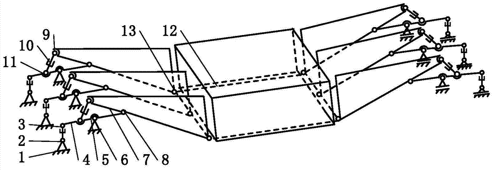
[0014] In the present invention figure 1 , figure 2 , image 3 with Figure 4 In the schematic diagram of , three bases A1 are placed on a horizontal plane, and the upper part of each base A is respectively connected to the fixed end of an adjusting cylinder 2, and the piston rod of the adjusting cylinder is hinged to one end of the support beam 4 through a hinge A3. The lower end in the middle of each supporting beam is connected with the upper end of the base B6 through a ball joint A5. The other end of each support beam is hinged with the lower end of the pincer beam 7 middle part by hinge B8. One end of the pincer beam is hinged with the upper part of the ball joint B9, the lower part of the ball joint B is connected with the piston rod of the lifting cylinder 10, and the fixed end of the lifting cylinder is hinged with the upper end of the support beam middle part through the ball joint C11. The other end of the pincer beam is respectively hinged with one side of the...


PUM


Abstract

A four-degree-of-freedom multilayer parallel lifting mechanism for a clamp car mainly comprises bases A, adjustment oil cylinders, hinges A, supporting beams, spherical hinges A, bases B, forcipated beams, hinges B, spherical hinges B, lifting oil cylinders, spherical hinges C and a tray. The inner sides, at the two sides of goods, of the four-degree-of-freedom multilayer parallel lifting mechanism are opposite with the center line of the goods as the symmetry axis. According to the four-degree-of-freedom multilayer parallel lifting mechanism for the clamp car, the load capacity of the lifting mechanism is effectively improved, and the lifting mechanism can be used for lifting and transporting super-heavy goods; the work space of the lifting mechanism is effectively increased, the influence of unbalanced loading of the goods on the lifting mechanism is reduced, and the lifting mechanism can be used for transporting super-wide goods; due to the fact that a multi-drive coordinative working mode is adopted, the lifting mechanism can be used for loading and unloading goods more conveniently and more flexibly.

Description

technical field [0001] The invention relates to a four-degree-of-freedom multi-layer parallel over-constraint lifting mechanism. Background technique [0002] With the promotion of industrial upgrading and the implementation of energy-saving and emission-reduction strategic measures in China, UHV transformers, large-scale generators and other complete sets of ultra-high-power electrical appliances will be developed in the future. The weight of these large-scale energy equipment will reach nearly 1,000 tons. In order to ensure the safety of these special cargoes, higher requirements are put forward for the safety and reliability of its transport clamp vehicles. With the development of the above-mentioned special cargo transportation demand, domestic and foreign clamping vehicle technology is developing towards large-scale, ultra-high load, high safety and reliability. Therefore, it has become an urgent need in the field of railway transportation in my country to develop clam...

Claims


Application Information

Patent Timeline
Patent Type & Authority Patents(China)
IPC IPC(8): B61D3/16B61D45/00
CPCB61D3/166B61D45/00
Inventor 赵延治焦雷浩
Owner YANSHAN UNIV
Learn More