Film cutting device

A cutting device and film technology, applied in thin material handling, transportation and packaging, sending objects, etc., can solve problems such as wasting costs, miscutting, and delaying production efficiency, and achieve the goals of improving production efficiency, saving energy, and increasing yield Effect

Inactive Publication Date: 2016-04-06
SHANGHAI XIONGHAN IND
View PDF0 Cites 4 Cited by
  • Summary
  • Abstract
  • Description
  • Claims
  • Application Information

AI Technical Summary

Problems solved by technology

[0002] At present, when the cutting device in the machine cuts the film, it can only be sent forward by the conveying roller at the rear. Sometimes the edge of the film will be lifted or rolled up. Because it is an assembly line operation, it will cause the phenomenon of miscutting. Many defective products, wasting cost, delaying production efficiency

Method used


Image

  • Film cutting device
  • Film cutting device
  • Film cutting device

Examples


Embodiment Construction

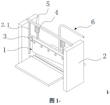
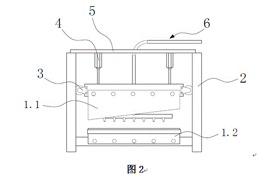
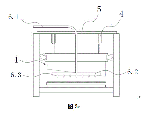
[0010] Such as figure 1 and figure 2 As shown, a film cutting device includes a cutting knife 1 and a wallboard 2, the cutting knife 1 includes an upper knife 1.1 and a lower knife 1.2, the top of the upper knife 1.1 is provided with several cylinders 4, and the cylinders are fixed on the beam 5, the two ends of the upper knife 1.1 are symmetrically provided with a guide wheel 3, and the wallboard is provided with a guide groove 2.1, and the guide wheel 3 cooperates with the guide groove 2.1, as image 3 As shown, the blowing device 6 is provided behind the cutting knife 1, and the blowing device 6 includes a blowing pipe 6.1 and a horizontal pipe 6.2, and one end of the conduit communicates with the middle part of the horizontal pipe 6.2. The bottom of the horizontal tube 6.2 is provided with several blowing heads 6.3. The horizontal pipe 6.2 also can directly have blowing holes below, and the technical effect is the same.

[0011] During use, the continuous film is pushe...


PUM


Abstract

The invention discloses a film cutting device which comprises a cut-off tool and wall boards. The cut-off tool comprises an upper tool body and a lower tool body. A plurality of air cylinders are arranged at the top of the upper tool body. The air cylinders are fixed to a crossbeam. Guide wheels are symmetrically arranged at the two ends of the upper tool body. Guide grooves are formed in the wall boards. The guide wheels are matched with the guide grooves. A blowing device is arranged behind the cut-off tool. The blowing device comprises a blowing pipe and a transverse pipe. One end of a guide pipe is communicated with the middle of the transverse pipe. The film cutting device is simple in structure; a film can be pressed downwards through airflow by means of the blowing device, the film is not prone to curling, the rate of finished products is increased, the production efficiency is improved, energy is saved, and the cost is reduced.

Description

technical field [0001] The invention relates to packaging machinery, in particular to a film cutting device. Background technique [0002] At present, when the cutting device in the machine cuts the film, it can only be sent forward by the conveying roller at the rear. Sometimes the edge of the film will be lifted or rolled up. Because it is an assembly line operation, it will cause the phenomenon of miscutting. Many defective products waste cost and delay production efficiency. Contents of the invention [0003] The purpose of the present invention is to solve the problems in the prior art, and propose a film cutting device, which can press down the film with airflow through the air blowing device, and is not easy to turn over. [0004] In order to achieve the above object, the present invention proposes a film cutting device, including a cutting knife and a wallboard, the cutting knife includes an upper knife and a lower knife, and several air cylinders are arranged on ...

Claims


Application Information

Patent Timeline
Patent Type & Authority Applications(China)
IPC IPC(8): B65H35/06B65H37/00
Inventor 朱凯敏
Owner SHANGHAI XIONGHAN IND
Why Eureka
Try Eureka