Washing machine deceleration clutch and washing machine

A deceleration clutch and washing machine technology, which is applied in the field of washing machines, can solve the problems of waste of space at the bottom and achieve the effects of increasing washing capacity, reducing axial space, and facilitating assembly

Active Publication Date: 2016-04-06
QINGDAO HAIER WASHING MASCH CO LTD +1
View PDF5 Cites 1 Cited by
  • Summary
  • Abstract
  • Description
  • Claims
  • Application Information

AI Technical Summary

Problems solved by technology

[0005] Since the deceleration clutch of the washing machine is installed at the bottom of the outer tub / drum, and the diameter of the outer tub / drum is much larger than that of the deceleration clutch, there is still a large space around the deceleration clutch, and no other structures are installed in this part of the space, resulting in The bottom space is wasted, and the motor, deceleration device and clutch device of the deceleration clutch are arranged in sequence along the axial direction, which also causes a waste of bottom space. Therefore, how to reasonably arrange the clutch device, deceleration device and motor of the deceleration clutch to reduce The overall height of the deceleration clutch increases the washing capacity of the washing machine, which has become a technical problem that needs to be solved urgently

Method used


Image

  • Washing machine deceleration clutch and washing machine
  • Washing machine deceleration clutch and washing machine
  • Washing machine deceleration clutch and washing machine

Examples


Embodiment 1

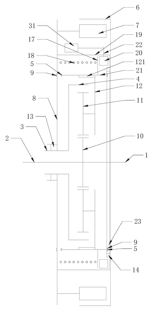
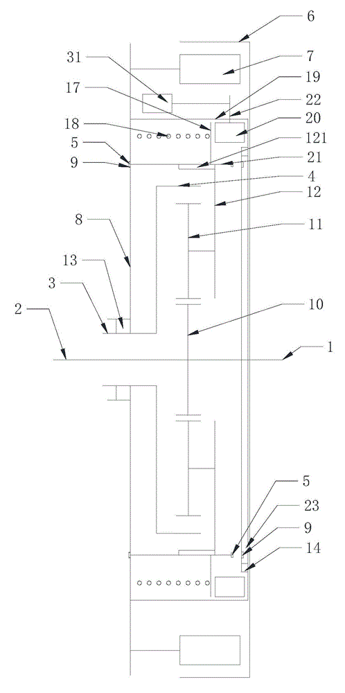
[0073] Such as figure 1 , figure 2 As shown, the clutch drive mode of a deceleration clutch of a washing machine described in this embodiment: the clutch device at least includes a clutch bushing 21 and a driving device for driving the clutch bushing 21 to move axially, and the clutch bushing 21 is arranged at the deceleration On the periphery of the device, the clutch bushing 21 is connected to the transmission gear carrier 12 in an axially relatively sliding and circumferentially non-rotatable manner, and the inner ring gear 4 is connected to the output bushing 3 .

[0074] The driving device at least includes a clutch pressure plate 20 coaxially arranged with the clutch sleeve 21 and its end surface has a height difference in the axial direction. The clutch pressure plate 20 rotates in the circumferential direction to drive the clutch sleeve 21 to move axially, and controls the output shaft. 2 and the different output states of the output sleeve 3.

[0075] One end of th...

Embodiment 2

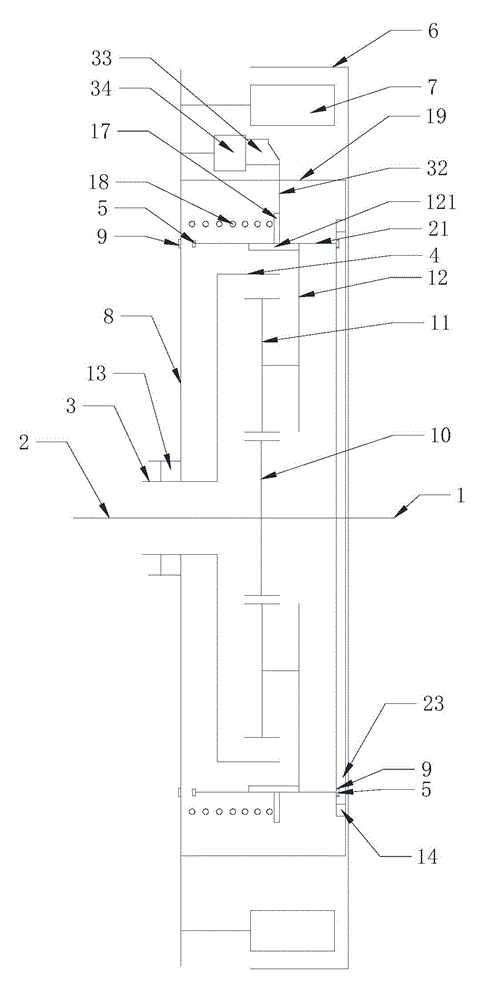
[0090] Such as image 3 , Figure 4 As shown, the clutch drive mode of a deceleration clutch of a washing machine described in this embodiment: the clutch device at least includes a clutch bushing 21 and a driving device for driving the clutch bushing 21 to move axially, and the clutch bushing 21 is arranged at the deceleration On the periphery of the device, the clutch bushing 21 is connected to the transmission gear carrier 12 in an axially relatively sliding and circumferentially non-rotatable manner, and the inner ring gear 4 is connected to the output bushing 3 .

[0091]The driving device is arranged on the periphery of the clutch sleeve 21 in the circumferential direction. The driving device does not occupy the height of the axial direction alone, and can further reduce the overall height of the deceleration clutch, occupying less axial space and leaving more space in the axial direction Place the washing tub / drum to make more effective use of space and improve the uti...

Embodiment 3

[0106] A washing machine having the deceleration clutch described in the first or second embodiment above, the washing machine is a pulsator washing machine or a drum washing machine.


PUM


Abstract

The invention relates to a washing machine deceleration clutch comprising an input shaft, a deceleration device, a clutch device, an output shaft and an output shaft sleeve. The deceleration device is at least formed by a central gear, a transmission gear, a transmission gear rack and an internal gear ring; the clutch device at least comprises a clutch shaft sleeve and a driving device driving a clutch shaft sleeve to axially move; the clutch shaft sleeve is mounted on the circumferential periphery of the deceleration device; the clutch shaft sleeve and the transmission gear rack can axially slide to each other, but cannot be circumferentially rotationally connected; the internal gear ring is connected with the output shaft sleeve; the driving device comprises at least one clutch platen coaxially arranged with the clutch shaft sleeve; the end surface of the clutch platen has height difference in an axial direction; the clutch platen circumferentially drives the clutch shaft sleeve to axially move to control different output states of the output shaft and the output shaft sleeve. The washing machine deceleration clutch is simply structured and occupies little space in an axial direction; and overall height of the deceleration clutch can be reduced and washing capacity can be increased.

Description

technical field [0001] The invention relates to the field of washing machines, in particular to a washing machine deceleration clutch and a washing machine with the deceleration clutch. Background technique [0002] Washing machines are household appliances commonly used in people's daily life. They are installed in different ways and can be divided into drum washing machines and pulsator washing machines. A drum washing machine generally includes an outer tub, a drum and a motor, and the motor drives the drum to rotate in the outer tub to wash or dehydrate the clothes. Present drum washing machines simply utilize the rotation of the drum for washing, and only use the lifting ribs in the drum to lift and drop the laundry to beat the clothes for washing, so it is difficult to obtain excellent washing effect. The current drum washing machine also has a pulsator in the drum, and the pulsator and the drum are respectively driven by independent motors to optimize the washing eff...

Claims


Application Information

Patent Timeline
Patent Type & Authority Applications(China)
IPC IPC(8): D06F37/30
Inventor 栾厚利翟清明李作强王珊徐超杜会防
Owner QINGDAO HAIER WASHING MASCH CO LTD
Why Eureka
Try Eureka