

Cooling and filtering structure of engine oil pump
A technology of oil pump and cooler, which is applied in the direction of engine cooling, mechanical equipment, engine components, etc. It can solve problems affecting engine lubrication performance and efficiency, increase hidden dangers of water leakage, and pollute engine oil, so as to improve installation efficiency and assembly quality , Disassembly and maintenance are convenient, and the effect of improving safety
- Summary
- Abstract
- Description
- Claims
- Application Information
AI Technical Summary
Problems solved by technology
Method used
Image

Examples
Embodiment Construction
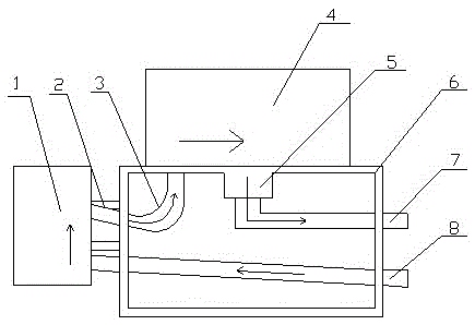
[0009] Such as figure 1 As shown, the present invention discloses a cooling and filtering structure of an oil pump, including an oil outlet pipe 8, a cooler assembly 1, an oil passage 3, a filter 4, an oil return pipe 7 and an accessory enamel 6;
[0010] The accessory enamel 6 has a horizontal top plane and a vertical side plane; the cooler assembly 1 is fixedly installed on the side plane of the accessory enamel 6; the filter 4 is installed on the top plane of the accessory enamel 6; one end of the oil outlet pipe 8 It is connected to the cooler assembly 1 with an upward slope, and the oil passage 3 is passed between the cooler assembly 1 and the filter 4; the oil return pipe is connected to the filter 4.
[0011] There is a support 2 for the cooler assembly 1 to be installed on the side plane of the accessory enamel 6 .
[0012] One end of the oil outlet pipe 8 is connected to the oil pump assembly, and the pressurized oil delivered from the pump body of the oil pump assem...
PUM
 Abstract
Description
Claims
Application Information