an oil filter

A technology of oil filter and filter element, which is applied in the installation/connection of lubricant purification device, lubricating parts, pressure lubricant, etc., which can solve the problems of inconvenient operation, complicated processing technology, and short service life of the filter element, and achieve Novel way of oil circuit, high filtration precision, and the effect of increasing the dirt holding capacity

Active Publication Date: 2019-08-09
GANSU HENGTONG FILTER IND
View PDF1 Cites 0 Cited by
  • Summary
  • Abstract
  • Description
  • Claims
  • Application Information

AI Technical Summary

Problems solved by technology

However, the oil path of the oil filter element is still the traditional way of filtering from the oil inlet hole - the outer surface of the filter element - the central tube with holes - the oil outlet hole. With the structure of the central tube support, all filter materials have the same particle size and the same density inside the filter bag. During the filtration process, large particles of impurities will block and harden near the outer surface of the filter bag, making it difficult to reach a deep level of filtration, and the service life of the filter element is short. And only one kind of filter material can be used for filtering, the filtering method is single, the filter course is short and the precision is low, deep filtration cannot be performed, and the filter material can not be conveniently selected to be used flexibly under different needs. Putting it into a long bag, and then winding it on the central tube by hand, the processing technology is complex and difficult to operate, especially for small filters, which is difficult to wind, which is not conducive to mechanized quantitative production. very limited in production

Method used


Image

  • an oil filter
  • an oil filter
  • an oil filter

Examples


Embodiment Construction

[0023] Below in conjunction with accompanying drawing and specific embodiment the present invention is described in further detail:

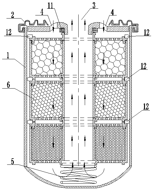
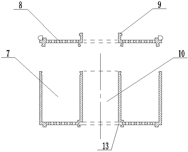
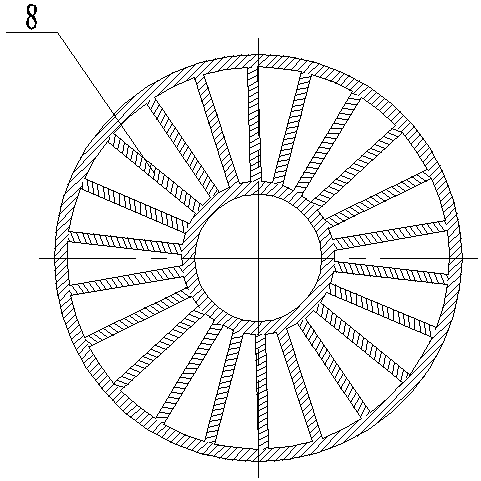
[0024] Such as figure 1 , figure 2 , image 3 As shown, an oil filter includes a housing 1, the upper end of the housing 1 is provided with a threaded cover plate 2, the center of the threaded cover plate 2 is provided with an oil outlet hole 3, and the outer circumference of the threaded cover plate 2 on the outer side of the oil outlet hole 3 A number of oil inlet holes 4 are provided. There is a support spring 5 at the inner bottom of the housing 1. The maximum bearing pressure of the support spring 5 in a static state is set according to customer requirements and the size of the filter. The housing 1 above the support spring 5 is equipped with a plurality of filter elements 6 assembled up and down. The formed filter element, when the hole of the filter element assembly 6 is blocked or the oil temperature is too low and the viscosity is h...


PUM


Abstract

The invention discloses an oil filter which comprises a shell. A threaded cover plate is arranged at the upper end of the shell. An oil outlet hole is formed in the center of the threaded cover plate. Oil inlet holes are circumferentially formed in the position, on the outer side of the oil outlet hole, of the threaded cover plate. A supporting spring is arranged at the bottom in the shell, and a filter element formed by vertically assembling a plurality of filter element assemblies is arranged at the position, above the supporting spring, in the shell. Each filter element assembly comprises a filter box center pipe and a filter box located on the outer side of the filter box center pipe. The filter box center pipes are in butt joint to form a filter element center pipe communicated with the oil outlet hole. The filter boxes are filled with filter materials. Upper end covers are arranged at the top of the filter element, and a plurality of holes are formed in the bottoms of the upper end covers and the bottoms of the filter boxes. A check sealing ring is arranged between the threaded cover plate and the upper end cover of the top-layer filter element assembly, and a sealing ring is arranged between the shell and the filter element. Deep adsorption is achieved in the filter process of the oil filter, the structure is simple, the oil path manner is novel, and a filter material is convenient and flexible to replace; and good universality is achieved, the filter effect is good, and the oil filter can be applied to industrial production.

Description

technical field [0001] The invention belongs to the technical field of lubricating oil purification device systems for mechanical equipment, and in particular relates to an engine oil filter widely used in internal combustion units. Background technique [0002] At present, the filters widely used in domestic and foreign engines all adopt corrugated paper type, metal mesh type, metal mesh type plus corrugated paper type, and centrifugal rotary filter. The oil filtration method of filters with these structures is generally full flow However, full-flow filters are not effective in filtering particles below 10 μm. They have small dirt holding capacity, low filtration efficiency, and short service life. , The filtering capacity of the filter element is greatly reduced. Therefore, at present, all engines (internal combustion machinery) must replace engine oil and filter elements on time and regularly to ensure the normal lubrication conditions required by the engine. In order t...

Claims


Application Information

Patent Timeline
Patent Type & Authority Patents(China)
IPC IPC(8): F01M11/03
CPCF01M11/03
Inventor 张兆彦张吉跃包哲铭李佳燕王浩吉包梦
Owner GANSU HENGTONG FILTER IND
Why Eureka
Try Eureka