
Pump and automatic putting system provided with same

A pump cavity and pump body technology, applied in the field of automatic feeding system, can solve the problems of increasing the difficulty of parts management, inconvenient installation, large volume, etc., and achieve the effect of convenient control program design, saving space and cost, and high degree of customization

Active Publication Date: 2016-04-06
JIANGSU LEILI MOTOR
View PDF6 Cites 10 Cited by
  • Summary
  • Abstract
  • Description
  • Claims
  • Application Information

AI Technical Summary

Problems solved by technology

Although the double-pump solution is reliable, it is bulky, troublesome to install, low utilization rate, and high cost. Although the cost of the one-valve-one-pump solution has been reduced, other shortcomings still exist, and the reliability has deteriorated. Therefore, it is urgently needed in the industry. Reliable, small in size, easy to install, and low-cost automatic delivery system products; in addition, there are devices that drive multiple pumps with a single power source in the prior art, but indirect drive is usually used to drive multiple pumps with a single power source, and Requires the opposite clutch mechanism to drive, the structure is more complicated, and it increases the difficulty of parts management, inconvenient installation, and high cost

Method used


Image

  • Pump and automatic putting system provided with same
  • Pump and automatic putting system provided with same
  • Pump and automatic putting system provided with same

Examples


Embodiment 1

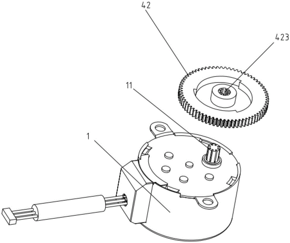
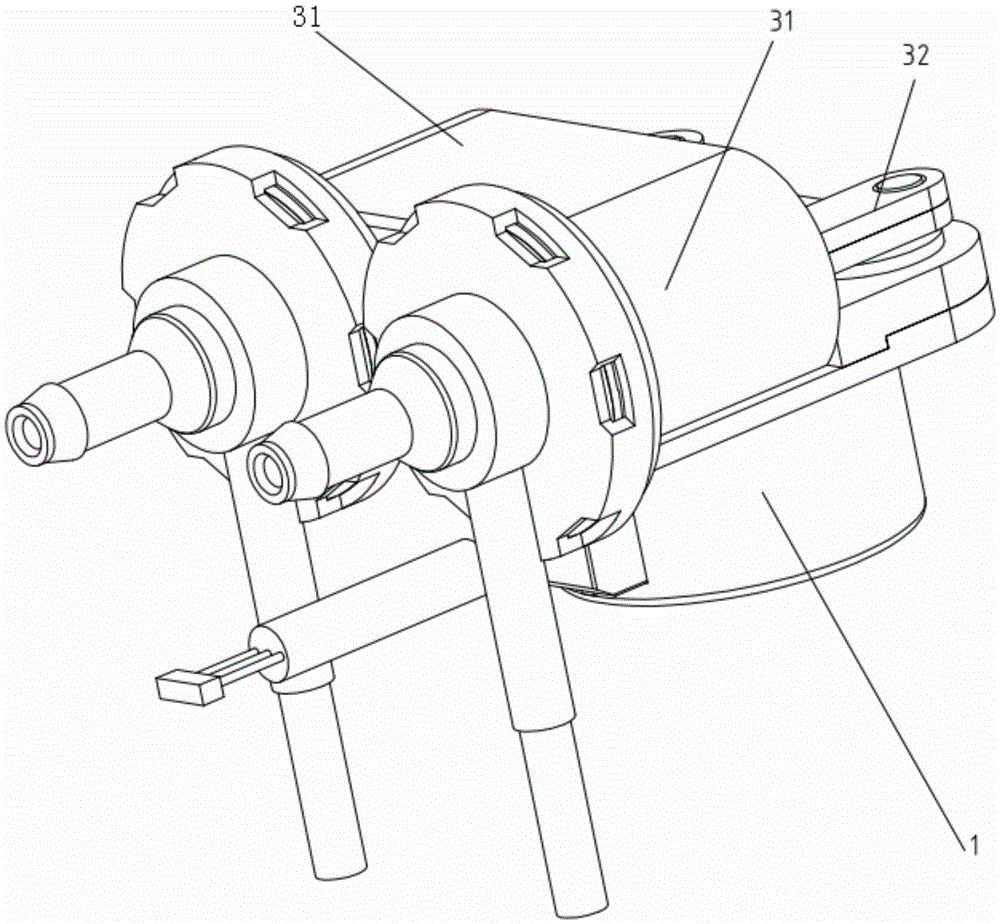
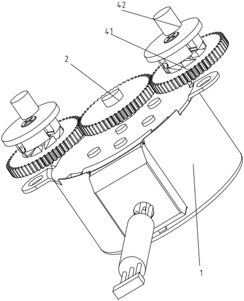
[0056] Such as Figure 1-7 , Shown in 14, a kind of pump, it comprises:

[0057] A power source 1 capable of forward and reverse power output; the power source 1 can be a motor;

[0058] A pump body 3, the pump body 3 has at least two pump chambers 31, and each pump chamber 31 is correspondingly provided with a pump chamber driving assembly 32;

[0059] At least two clutch mechanisms, the clutch mechanisms correspond to the pump chambers 31 one by one, and the clutch mechanisms are connected to the pump chamber driving components 32 of the corresponding pump chambers 31, when the power source 1 rotates forward to output power or when the power source 1 When the power output is reversed, at least one of the clutch mechanisms is in the power engagement state and at least one of the clutch mechanisms is in the power separation state, and the power source transmits power to the corresponding pump chamber drive assembly 32 through the clutch mechanism in the power engagement state...

Embodiment 2

[0081] Such as Figures 9 to 17 Shown, a kind of pump, it comprises:

[0082] A power source 1 capable of forward and reverse power output; the power source 1 can be a motor;

[0083] The pump body 3, the pump body 3 has at least two pump chambers 31, and each pump chamber 31 is correspondingly provided with a pump chamber driving assembly 32; at least two clutch mechanisms, the clutch mechanisms correspond to the pump chambers 31 one by one, and the The above-mentioned clutch mechanism is connected with the pump chamber drive assembly 32 of the corresponding pump chamber 31, when the power source 1 rotates the power output in the forward direction or when the power source 1 reverses the power output, at least one of the clutch mechanisms is in the power engagement state and at least one The power separation of the clutch mechanism is in the power separation state, and the power source transmits power to the corresponding pump chamber drive assembly 32 through the clutch mech...


PUM


Abstract

The invention discloses a pump and an automatic putting system provided with the same. The pump comprises a power source capable of rotating forwardly or reversely to output power, a pump body and at least two clutch mechanisms, wherein the pump body is provided with at least two pump cavities, and each pump cavity is correspondingly provided with a pump cavity driving assembly; the clutch mechanisms are in one-to-one correspondence with the pump cavities and are connected with the pump cavity driving assemblies of the corresponding pump cavities. When the power source rotates forwardly or reversely to output power, at least one clutch mechanism is in a power connection state, at least one clutch mechanism is in a power separation state, and the power source transmits the power to the corresponding pump cavity driving assemblies through the clutch mechanisms in the power connection state to make the corresponding pump cavities work. The pump can achieve the function that a single power source drives multiple pump cavities to work, and is high in integration degree, good in reliability, convenient to install, capable of saving energy and low in manufacture cost.

Description

technical field [0001] The invention relates to a pump and an automatic feeding system using the pump, belonging to the technical fields of washing machines and dishwashers. Background technique [0002] At present, most of the automatic dispensing systems designed by washing machine manufacturers are required to be able to dispense two solutions, such as detergent and softener, respectively. At present, the automatic dosing system using the dosing pump on the market mainly adopts two solutions to realize the separate dosing of the two solutions. One is to use two unit pumps to pump two solutions separately; the other is to use one unit pump and a reversing valve assembly to switch the pumped solution through the reversing valve assembly. Although the double-pump solution is reliable, it is bulky, troublesome to install, low in utilization rate, and high in cost. Although the cost of the one-valve-one-pump solution has been reduced, other shortcomings still exist and its re...

Claims


Application Information

Patent Timeline
Patent Type & Authority Applications(China)
IPC IPC(8): F04B17/00F04B43/02
CPCF04B17/00F04B43/02
Inventor 殷立威王小强
Owner JIANGSU LEILI MOTOR
Learn More