
Ultralow-temperature vacuum draught fan

An ultra-low temperature, vacuum technology, used in mechanical equipment, machines/engines, liquid fuel engines, etc., can solve the problem of not being able to meet the requirements, and achieve the effect of increasing strength

Inactive Publication Date: 2016-04-06
ZHENJIANG DANTU DISTRICT FOOD FACTORY
View PDF5 Cites 2 Cited by
  • Summary
  • Abstract
  • Description
  • Claims
  • Application Information

AI Technical Summary

Problems solved by technology

[0002] Sometimes it is necessary to create an ultra-low temperature vacuum environment in the laboratory, which is generally achieved by using a vacuum pump, but the temperature of the vacuum environment produced by the vacuum pump is generally about -20°C, which is far from reaching the required temperature.

Method used


Image

  • Ultralow-temperature vacuum draught fan
  • Ultralow-temperature vacuum draught fan
  • Ultralow-temperature vacuum draught fan

Examples


Embodiment Construction

[0023] The present invention will be further described below in conjunction with the accompanying drawings.

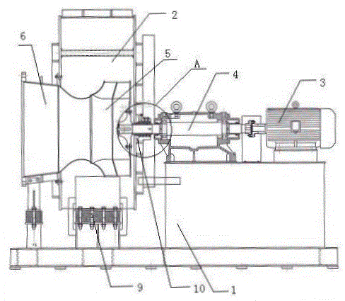
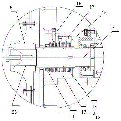
[0024] As shown in the figure, an ultra-low temperature vacuum fan includes a machine base 1, a casing 2, a motor 3, a main shaft 4, an impeller assembly 5 and an air inlet ring 6, and the outside of the casing 2 is provided with a reinforcing rib group 7, and the reinforcement The rib group 7 is composed of several rings of reinforcing ribs 8, the casing 2 is fixed above the base 1, and a cold bridge 9 is provided between the casing 2 and the base 1, and the cold bridge 9 is made of polytetrafluoroethylene Prepared, the impeller assembly 5 is fixed in the casing 2, one end of the impeller assembly 5 is connected to the air inlet ring 6, and the other end is connected to the motor 3 through the main shaft 4, and the motor 3 is fixed on the base 1, The main shaft 4 passes through the casing 2, the main shaft 4 is made of 16Mn, and a sealing structure 10 is provided betw...


PUM


Abstract

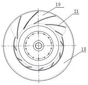
The invention relates to an ultralow-temperature vacuum draught fan which comprises a machine base, a machine shell, a motor, a main shaft, an impeller assembly and an air inlet ring. The machine shell is fixed to the upper portion of the machine base. A cold bridge is arranged between the machine shell and the machine base. The cold bridge is prepared from a polytetrafluoroethylene material. The impeller assembly is fixed into the machine shell. One end of the impeller assembly is communicated with the air inlet ring, and the other end of the impeller assembly is connected with the motor. The motor is fixed to the machine base. The main shaft penetrates the machine shell. A sealing structure is arranged between the main shaft and the machine shell. The impeller assembly comprises a front disc, a middle disc, a rear disc, first blades, second blades and a rotating shaft. The ultralow-temperature vacuum draught fan is used for manufacturing an ultralow-temperature vacuum environment, and the temperature can be lowered to -80 DEG C or even lower.

Description

technical field [0001] The invention relates to a fan, in particular to an ultra-low temperature vacuum fan. Background technique [0002] Sometimes it is necessary to create an ultra-low temperature vacuum environment in the laboratory, which is generally achieved by using a vacuum pump, but the temperature of the vacuum environment produced by using a vacuum pump is generally about -20°C, which is far from meeting the requirements. Contents of the invention [0003] The technical problem to be solved by the present invention is to provide an ultra-low temperature vacuum blower for the above disadvantages, which is used to create an ultra-low temperature vacuum environment, and the temperature can be as low as -80°C or lower. [0004] In order to solve the problems of the technologies described above, the technical solution of the present invention is: [0005] An ultra-low temperature vacuum fan, including a machine base, a casing, a motor, a main shaft, an impeller ass...

Claims


Application Information

Patent Timeline
IPC IPC(8): F04D17/10F04D29/12F04D29/58F04D29/28F04D29/30F04D29/02F04D29/42F04D29/053
CPCF04D17/10F04D29/023F04D29/053F04D29/122F04D29/281F04D29/30F04D29/4226F04D29/582F05D2300/11F05D2300/431
Inventor 徐洋袁逸如王蓉蓉
Owner ZHENJIANG DANTU DISTRICT FOOD FACTORY
Learn More