Swirl vane and flue gas ammonia-injection and denitration device

A swirling blade and flue gas technology, applied in gas treatment, fluid flow, chemical instruments and methods, etc., can solve the problem of uneven mixing of reducing agent and flue gas, and achieve simple structure, low installation space requirements, and investment. low cost effect

Active Publication Date: 2016-04-06
NORTH CHINA ELECTRICAL POWER RES INST +1
View PDF6 Cites 7 Cited by
  • Summary
  • Abstract
  • Description
  • Claims
  • Application Information

AI Technical Summary

Problems solved by technology

[0009] In order to solve the existing technical problem of uneven mixing of reducing agent and flue gas in the flue

Method used


Image

  • Swirl vane and flue gas ammonia-injection and denitration device
  • Swirl vane and flue gas ammonia-injection and denitration device
  • Swirl vane and flue gas ammonia-injection and denitration device

Examples


Embodiment Construction

[0034] It should be noted that, in the case of no conflict, the embodiments in the present application and the features in the embodiments can be combined with each other. The present invention will be described in detail below with reference to the accompanying drawings and examples.

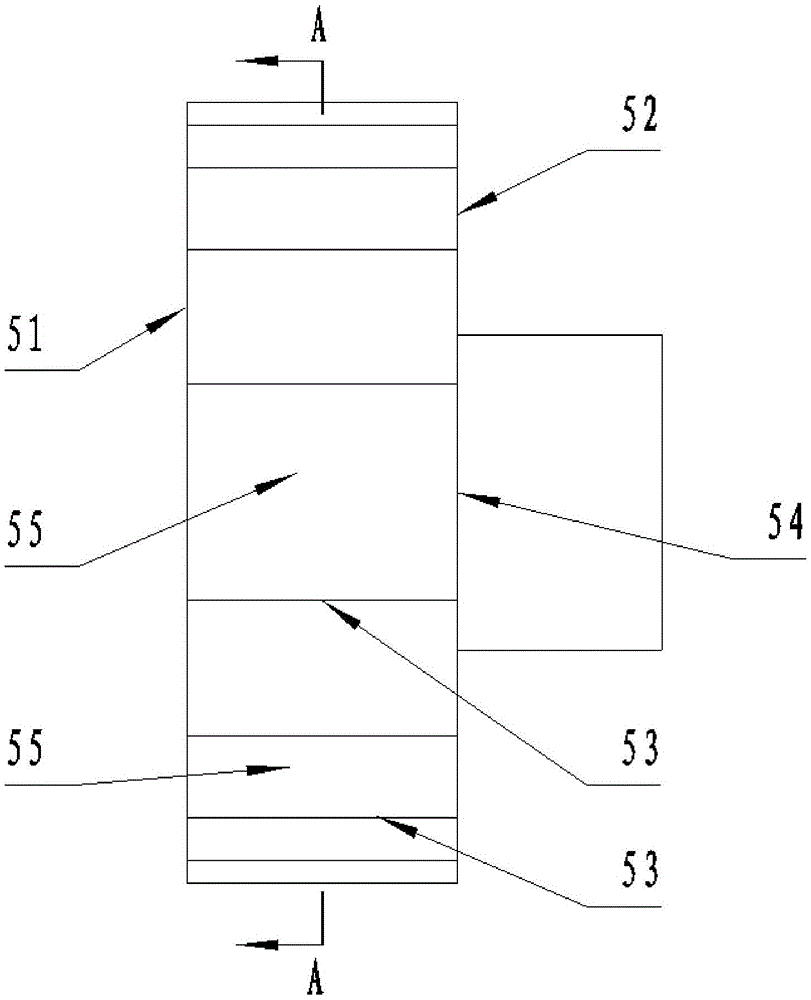
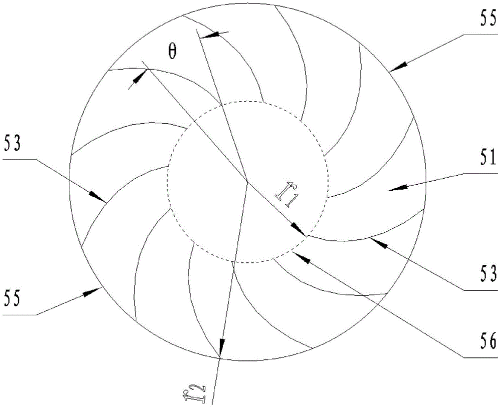
[0035] In order to make the concentration distribution of the gas components on the flue cross-section tend to be uniform, the present invention provides a swirl vane, which is a lateral air inlet structure, including two first partitions 51 and a second partition parallel to each other. Two baffles 52, a plurality of baffles 53 are uniformly distributed between the first baffle 51 and the second baffle 52, the middle part of the second baffle 52 contains an air outlet 54, the adjacent two baffles 53 Between the outer ends is the air inlet 55, and between the inner ends of the two deflectors 53 is the inner outlet 56, and the air flow can flow out of the swirl blade after passing through the ai...


PUM


Abstract

The invention provides a swirl vane and a flue gas ammonia-injection and denitration device. The swirl vane comprises a first partition plate (51) and a second partition plate (52) which are parallel to each other, wherein a plurality of flow deflectors (53) are arranged between the first partition plate (51) and the second partition plate (52); the middle part of the second partition plate (52) is provided with an air outlet (54); an air inlet (55) is arranged between outer ends of adjacent two flow deflectors (53); an inner outlet (56) is arranged between inner ends of the two flow deflectors (53); and gas flow can sequentially pass through the air inlets (55), the inner outlets (56) and the air outlet (55), and then flows out of the swirl vane. After being optimized, the swirl vane can enable the gas component concentration distribution on a flue section to be uniform in case of not needing to additionally applying power and energy. On the primes of not increasing NOx measuring points, the effect of automatically control flow of a reducing agent is brought into play, and optimized operation of a denitration system is realized.

Description

technical field [0001] The invention relates to the technical field of environmental protection devices, in particular to a swirl blade and a device for flue gas spraying ammonia and denitrification. Background technique [0002] During the operation of the boiler, the flow rate of SCR (selective catalytic reduction) reducing agent is too small, and the NOx concentration in the flue gas at the SCR outlet cannot meet the national emission standards; the flow rate of reducing agent is too large, and part of the NH 3 If it does not fully react with NOx, it will be further converted into ammonium bisulfate, causing blockage of the flue on the heating surface after the SCR. Therefore, on the premise of ensuring that the NOx concentration at the SCR outlet reaches the standard, reducing the amount of reducing agent used is the main purpose of the automatic control of the flow rate of the SCR reducing agent. [0003] In the flue gas at the outlet of the SCR, the distribution of ga...

Claims


Application Information

Patent Timeline
Patent Type & Authority Applications(China)
IPC IPC(8): F15D1/04B01D53/90B01D53/86
CPCB01D53/8631B01D53/90B01D2251/2062B01D2258/0283F15D1/04
Inventor 李金晶杜磊李媛园赵振宁张清峰付俊杰韩志成赵计平
Owner NORTH CHINA ELECTRICAL POWER RES INST
Why Eureka
Try Eureka