
Method for designing intelligent vibration isolation control system of flexible buoyant raft

A control system and design method technology, applied in non-rotational vibration suppression, ship propulsion, ship components, etc., can solve the problem that the floating raft vibration isolation system has not realized the intelligent universal wide-band design, and the design of the intelligent controller for observation overflow is complicated , Vibration isolation active control system is prone to problems such as control overflow, which achieves the effect of facilitating industrialization and high execution efficiency

Inactive Publication Date: 2016-04-06
SHENYANG AEROSPACE UNIVERSITY
View PDF5 Cites 5 Cited by
  • Summary
  • Abstract
  • Description
  • Claims
  • Application Information

AI Technical Summary

Problems solved by technology

[0003] The existing floating raft vibration isolation system has not realized the intelligent general-purpose wide-band design. The floating raft vibration isolation system includes three parts: configuration design, dynamic modeling, and control system design. The existing modeling method makes the vibration isolation Active control systems are prone to control overflow, observation overflow and difficult to realize the complex design of intelligent controllers, which limit the application of active vibration isolation technology in actual engineering

Method used


Image

  • Method for designing intelligent vibration isolation control system of flexible buoyant raft
  • Method for designing intelligent vibration isolation control system of flexible buoyant raft
  • Method for designing intelligent vibration isolation control system of flexible buoyant raft

Examples


Embodiment Construction

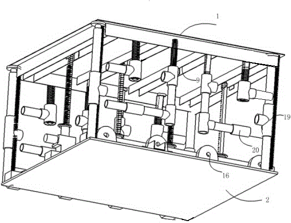
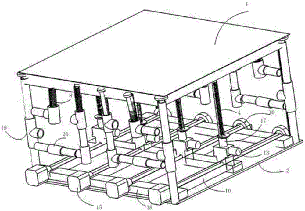
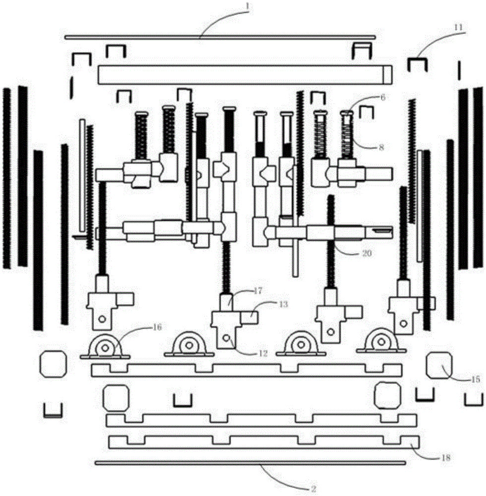
[0049] Such as Figure 1-Figure 4As shown, an intelligent vibration isolation system for a flexible floating raft includes a raft frame (1), a fixed bottom plate (2), a spring guide rod (3), a movable support spring (4), a four-corner push rod (5), a side top Rod (6), four-corner vibration isolation spring (7), side spring (8), top chute (9), bottom chute (10), top slider (11), bottom slider (12), motor Reducer assembly (13), lead screw (14), stepping motor (15), sensor and non-self-locking limit switch, wherein the raft frame (1) arranged above and the fixed bottom plate (2) arranged below are used For the parts that are fixedly connected between them, a spring guide rod (3) is arranged between the raft (1) and the fixed bottom plate (2), and the spring guide rod (3) is embedded in the movable In the support spring (4), a four-corner push rod (5) and a side push rod (6) are respectively arranged on the four sides of the raft frame (1) and the fixed base plate (2), and the fo...


PUM

PropertyMeasurementUnit
Sensitivityaaaaaaaaaa

Abstract

The invention aims at providing a method for designing an intelligent vibration isolation control system of a flexible buoyant raft. The method includes the steps that firstly, the arrangement numbers and the assembling positions of sensors, stepping motors, stepping motor drivers, non-self-locking limiting switches, power sources of the non-self-locking limiting switches and motor reducer combinations are determined according to a structural drawing of the vibration isolation control system of the flexible buoyant raft; secondly, the models of the sensors, the stepping motors, the stepping motor drivers, the motor reducer combinations, the non-self-locking limiting switches and the power sources of the non-self-locking limiting switches are selected; thirdly, the sensors, the stepping motors, the stepping motor drivers, drive power sources, the motor reducer combinations, the non-self-locking limiting switches, the power sources of the non-self-locking limiting switches and a Dspace are connected with wires and installed; fourthly, a MATLAB / Simulink control algorithm is designed and related channels are arranged; and fifthly, the MATLAB / Simulink control algorithm is downloaded to Dspace hardware, and online operation and monitoring are performed. The problems that control overflow and observation overflow are likely to happen and an intelligent controller is difficult to design in the prior art are solved.

Description

technical field [0001] The invention belongs to the technical field of vibration isolation systems, in particular to a design method for a flexible floating raft intelligent vibration isolation control system. Background technique [0002] The acoustic stealth ability of a submarine is one of the important factors related to its vitality and combat effectiveness, so reducing the vibration and noise level of a submarine is a very important task. Floating raft is a kind of vibration and noise reduction equipment widely used in submarines in various countries. It can significantly reduce the transmission of high-frequency vibration of equipment in the boat to the hull. It's not ideal. At present, the known dynamic modeling methods of floating raft vibration isolation systems mainly include multi-rigid body dynamic modeling methods, finite element dynamic modeling methods, impedance comprehensive modeling and analysis methods, modal impedance comprehensive modeling and analysis...

Claims


Application Information

Patent Timeline
IPC IPC(8): F16F15/04B63H21/30
CPCB63H21/302F16F15/04
Inventor 杨靖宇张杜江顾明铖崔轩鸣张靖宇刘智奇
Owner SHENYANG AEROSPACE UNIVERSITY
Learn More