Spiral feeding machine for disposing entangled rubbish

A screw feeder, garbage technology, applied in the direction of combustion method, combustion type, incinerator, etc., to achieve the effect of avoiding economic loss, avoiding odor overflow, and avoiding cleaning work

Inactive Publication Date: 2016-04-06
SHENWU TECH GRP CO LTD
View PDF10 Cites 7 Cited by
  • Summary
  • Abstract
  • Description
  • Claims
  • Application Information

AI Technical Summary

Problems solved by technology

[0005] The technical problem to be solved by the present invention is to overcome the deficiencies in the prior art, and provide a screw feeder for dealing with the entanglement of garbage. The cylindrical shell or the screw blade is heated by a heating device, and then the screw feeder is treated by pyrolysis. The garbage entanglement and blockage of the feeder, and at the same time, avoid the disassembly and cleaning of the screw feeder

Method used


Image

  • Spiral feeding machine for disposing entangled rubbish
  • Spiral feeding machine for disposing entangled rubbish
  • Spiral feeding machine for disposing entangled rubbish

Examples


Embodiment 1

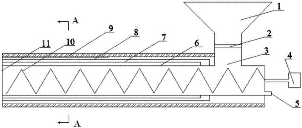
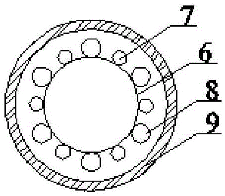
[0035] Preferably, the heating device is an electric heating tube 7, and the electric heating tube 7 is arranged along the outer wall of the cylindrical shell 6 or is arranged in the rotating shaft of the shafted helical blade, such as figure 1 As shown, the electric heating tube 7 is a tubular electric heating element, and when the spiral blade 10 is a shaftless spiral blade, the electric heating tube 7 is arranged on the outer wall of the cylindrical shell 6, and the insulation layer 9 is arranged outside the electric heating tube 7, so as to facilitate The surface of the cylindrical shell 6 is heated to indirectly heat the garbage in the screw feeder; when the screw blade 10 is a screw blade with a shaft, the electric heating tube 7 is arranged in the cavity in the rotating shaft of the screw blade 10 , the insulating layer 9 and the outer wall of the cylindrical housing 6 are arranged in close contact with each other so as to heat the garbage in the screw feeder.

[0036] ...

Embodiment 2

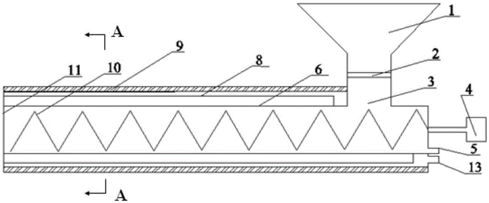
[0038] The difference between embodiment two and embodiment one is that the combustion heating device is arranged on the cylindrical housing 6 or in the rotating shaft of the spiral blade 10, when the combustion heating device is arranged on the cylindrical housing 6, the combustion heating device consists of The burner 12, the annular cavity between the cylindrical shell 6 and the insulation layer 9, and the flue gas outlet 13 arranged at the end of the annular cavity; when the combustion heating device is arranged in the rotating shaft of the spiral blade 10, the combustion The heating device is composed of a burner 12, a cavity in the rotating shaft and a flue gas outlet 13 arranged at the end of the cylindrical shell 6. The burner 12 can be arranged in the annular cavity, and also can be arranged in the rotating shaft of the shafted helical blade, wherein the burner 12 is preferably a gas burner, such as image 3As shown, the gas burner generally adopts an annular tubular ...

Embodiment 3

[0041] The difference between the third embodiment and the second embodiment is that the heating medium device is composed of a medium inlet, a medium channel 14 and a medium outlet, and the medium heating device is arranged on the cylindrical shell 6 or in the rotating shaft of the helical blade 10 . Such as Figure 5 As shown, the medium passage 14 is arranged in the annular cavity, and the hot air flow is passed into the medium passage 14. The hot air flow is preferably the hot flue gas in the incinerator, and the two ends of the medium passage 14 are respectively provided with a medium inlet and a medium outlet. The medium channel 14 can be arranged in the annular cavity, and can also be arranged in the cavity in the rotating shaft of the screw blade 10, then, the position of the insulation layer 9 is correspondingly arranged outside the annular cavity or on the outer wall of the cylindrical housing 6 , this design is to facilitate the hot air flow in the medium channel 14...


PUM


Abstract

The invention relates to the technical field of mechanical equipment for rubbish conveying and discloses a spiral feeding machine for disposing entangled rubbish. The spiral feeding machine for disposing the entangled rubbish comprises a cylindrical housing and spiral blades arranged in the cylindrical housing and further comprises a heating device for heating the cylindrical housing or the spiral blades, and a heat preservation layer is arranged outside the cylindrical housing or the heating device located on the cylindrical housing. The spiral feeding machine for disposing the entangled rubbish indirectly heats the rubbish in the spiral feeding machine by heating the surface of the cylindrical housing or the spiral blades to achieve rubbish pyrolysis, the problems of rubbish entangling and blockage of the spiral feeding machine are solved, and the dismounting and cleaning work of the spiral feeding machine is avoided.

Description

technical field [0001] The invention relates to the technical field of garbage conveying machinery and equipment, in particular to a screw feeder for dealing with entangled garbage. Background technique [0002] Domestic waste has a complex composition, mainly including kitchen waste, dust, bricks, paper, plastic, fabric, glass, metal, wood and bamboo, etc. When using garbage incinerators, garbage pyrolysis furnaces, etc. to treat garbage, in order to prevent the overflow of toxic and harmful gases during the garbage treatment process, resulting in deterioration of the operating environment, the sealing requirements for the feeding system are high. [0003] The overall structure of the screw conveyor is simple, the manufacturing cost is low, the sealing is good, the feeding is continuous and uniform, and the adjustment ratio is relatively accurate. . The screw feeder is often used in the feeding system of waste treatment, such as fluidized bed waste incinerator, rotary was...

Claims


Application Information

Patent Timeline
Patent Type & Authority Applications(China)
IPC IPC(8): F23G5/44F23G5/027
CPCF23G5/027F23G5/444F23G2201/30F23G2205/121
Inventor 陶进峰肖磊蔡先明刘璐吴道洪
Owner SHENWU TECH GRP CO LTD
Why Eureka
Try Eureka