
230M wireless collector

A wireless collector and wireless technology, applied in the direction of instruments, non-electrical signal transmission systems, signal transmission systems, etc., can solve the problems of easy breakage of SIM cards, mismatching terminal equipment, affecting the use of electric meters, etc., and achieve no traffic fee Effect

Inactive Publication Date: 2016-04-06
STATE GRID CORP OF CHINA +2
View PDF6 Cites 4 Cited by
  • Summary
  • Abstract
  • Description
  • Claims
  • Application Information

AI Technical Summary

Problems solved by technology

[0004] First, the environment where the electric meter is located is complex, with different conditions such as smog, ultraviolet rays, and high and low temperature differences. At this time, the SIM card is prone to deformation, poor contact, or temperature out of range, which makes the communication equipment unable to work normally and affects the meter reading rate of the electrical equipment.
[0005] Second, the total amount of SIM is huge, the installation is scattered, the cost of fault maintenance is high, and the installation site is unattended, so it is easy to be stolen, which affects the reliability and safety of users' electricity consumption;
[0006] The third is that the SIM card itself is easily broken and physically damaged, which affects the use of the meter
[0008] 1. The number of SIM cards is huge, and the SIM cards cannot be
[0009] 2. On-site installation and replacement need to carry a large number of SIM cards, which are prone to mixed insertion and wrong insertion during installation, resulting in a mismatch with the terminal equipment and hindering normal communication

Method used


Image

  • 230M wireless collector
  • 230M wireless collector

Examples


Embodiment

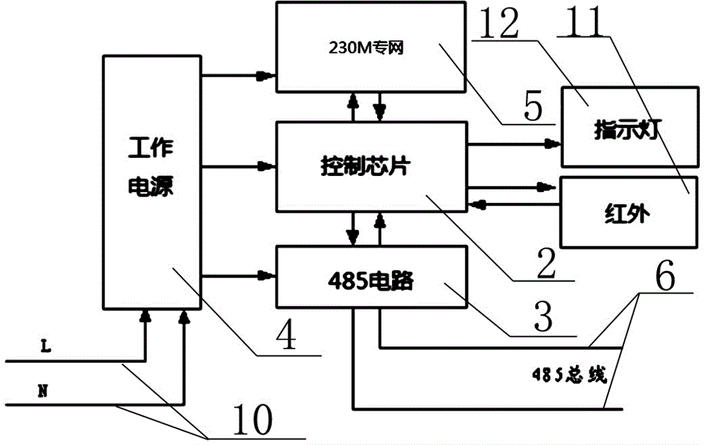
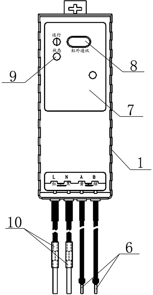
[0021] Embodiment: The present invention mainly consists of a shell and an internal circuit, wherein the shell 1 uses the shell of the State Grid II type collector, and the internal circuit is mainly composed of a control chip 2, a 230M private network communication module 5, a power supply 4, and a 485 circuit 3 , infrared 11, indicator light 12 composition.

[0022] The control chip 2 is mainly for processing data conforming to the State Grid Regulations. It is connected to the electric meter through the 485 circuit 3, and directly interacts with the electric meter for data interaction. It can process real-time data, store some frozen data, and so on.

[0023] The 230M private network communication module 5, the wireless part of which is mainly responsible for interacting with the 230M base station, the 230M base station is directly connected to the main station of the State Grid, and the wired part of the 230M private network communication module 5 is mainly connected to the...


PUM


Abstract

The invention provides a 230M wireless collector. The 230M wireless collector mainly comprises a shell, a control chip, a 485 circuit, a power source and a 230M private network communication module, wherein the control chip, the 485 circuit, the power source and the 230M private network communication module are installed in the shell. The control chip is connected with an electric meter through the 485 circuit and 485 wires and directly conducts data interaction with the electric meter, real-time data are processed, and several freeze frame data are stored. The control chip is connected with the wired part of the 230M private network communication module through a serial port, the 230M private network communication module conducts interactive connection with a 230M base station through the wireless part, and the 230M base station is directly connected with a state grid main station. A state grid II type collector shell is adopted as the shell, and a sucker receiving antenna, an infrared communication hole, an indicator light hole, a wire RS485A, a line RS485B, a power line L and a power line N which are internally connected with the wireless part of the 230M private network communication module are arranged on the shell. The 230M wireless collector has the advantages that wiring is easy, and the 230M wireless collector can work in severer environments.

Description

technical field [0001] The invention relates to a wireless collector for collecting real-time electric energy indications, daily zero-point frozen electric energy indications, and daily zero-point frozen electric energy indications of meter reading meters. Background technique [0002] At present, the remote meter reading method based on the power carrier wave or the remote meter reading method based on the public network GPRS power private network is mainly used. The problems of carrier wave meter reading are mainly problems such as large interference and slow meter reading time. Remote meter reading based on GPRS public network will mainly generate certain traffic charges. Due to the huge number of electric meters, huge costs will be generated every month, and this The fee is paid year after year, and the final statistics are also a very large expense. Not only is it a tariff issue, but also a physical SIM card must be used to use GPRS. Since the SIM card has strict requi...

Claims


Application Information

Patent Timeline
Patent Type & Authority Applications(China)
IPC IPC(8): G08C17/02G08C23/04
CPCG08C17/02G08C23/04
Inventor 朱萧轶陈理陈芳沈燕萍蒋海忠余允涛吴维维陈玉峰支慧蓉葛勇华肖敏英李芳珍汪泽州
Owner STATE GRID CORP OF CHINA
Learn More