LED drive power source self-discharge method and circuit module applicable to alternating-current dimmers

A technology of LED drive and AC dimmer, which is applied in the direction of light source, electric light source, electroluminescent light source, etc. It can solve the problems of low switching frequency, unreasonable physical parameters of damping circuit, and large power loss.

Active Publication Date: 2016-04-06
JIANGSU LIGEN ELECTRIC POWER ELECTRONICS TECH CO LTD
View PDF6 Cites 2 Cited by
  • Summary
  • Abstract
  • Description
  • Claims
  • Application Information

AI Technical Summary

Problems solved by technology

And in many switching power supply applications, when the input voltage is very small, the switching frequency is relatively low, so it is opposite to the demand of the dimmer
[0007] If only relying on the damping circuit to provide the corresponding holding current and trigger current, the physical parameters of the damping circuit will become unreasonable, which will directly lead to an increase in the cost and size of the circuit components, and cause excessive power loss

Method used


Image

  • LED drive power source self-discharge method and circuit module applicable to alternating-current dimmers
  • LED drive power source self-discharge method and circuit module applicable to alternating-current dimmers
  • LED drive power source self-discharge method and circuit module applicable to alternating-current dimmers

Examples


Embodiment Construction

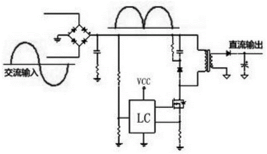
[0023] Such as figure 2 As shown, the present invention is applicable to drive structures including flyback, buck, boost, forward and other topologies. figure 2 The switching device in the flyback circuit shown can provide additional current by increasing the duty cycle and frequency. Among them, the damping circuit is used to assist in providing latch or gate trigger current.

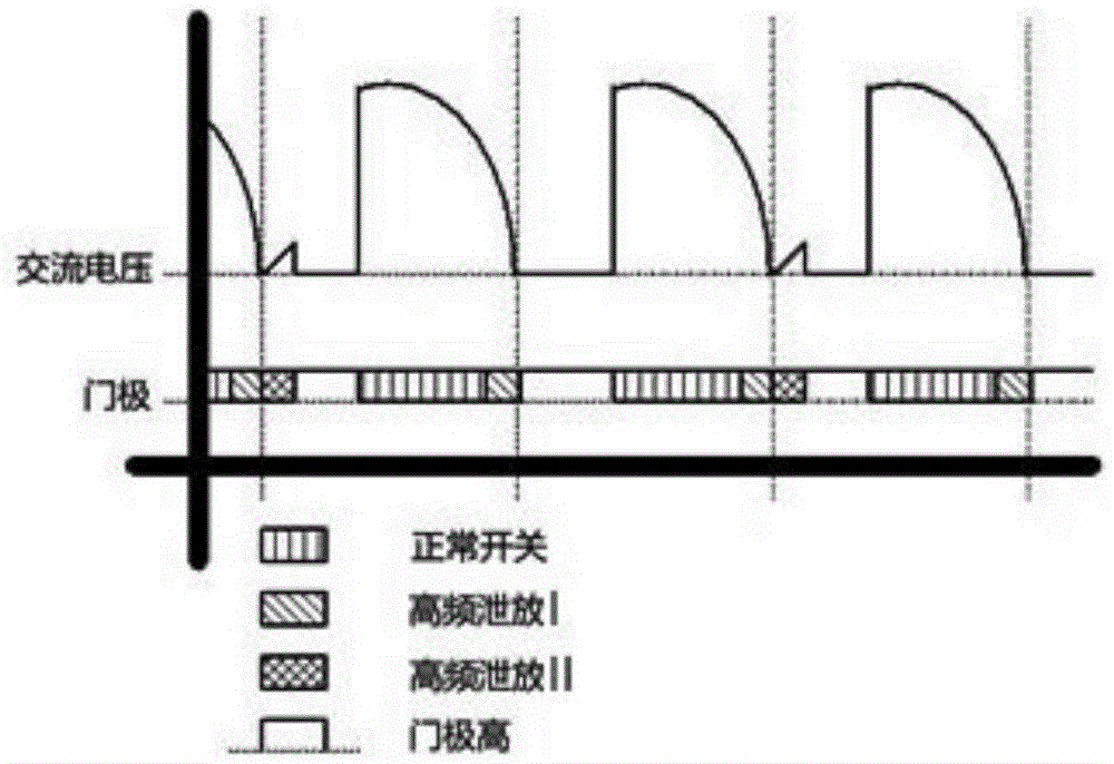
[0024] go to image 3 , as described in the background technology, there are still some shortcomings in the existing technology. In order to meet the load current requirements of most types of dimmers on the market, the present invention proposes a new solution without adding any new In the case of components, the additional load current is obtained by adjusting the switching frequency and duty cycle of the main switching device (such as a field effect transistor) through a program to help meet the dimmer's demand for maintaining current. image 3 The individual signals shown represent the AC inpu...


PUM


Abstract

The invention discloses an LED drive power source self-discharge method and a circuit module applicable to alternating-current dimmers. The LED drive power source self-discharge method applicable to alternating-current dimmers comprises the following steps: adjusting the switching frequency and duty ratio of a main switching device, and generating an additional load current on the input side of an LED drive circuit to meet the need of a dimmer for the holding current. According to the invention, the switching frequency of the main switching device is increased to enable the LED drive circuit to generate a certain current on the input side to meet the need of the dimmer, without increasing the power on the output side. The LED drive power source self-discharge method and the circuit module of the invention are applicable to a variety of power electronic topologies including boosting, bucking, forward activation and reverse activation.

Description

technical field [0001] The invention belongs to the field of LED switching power supplies, in particular to a self-discharging method and a circuit module of an LED driving power supply suitable for an AC dimmer. Background technique [0002] Existing dimmers and electronic transformers are mostly designed for resistive loads, and a minimum load is required to maintain the normal operation of the dimming and voltage regulating equipment. There are many kinds of existing dimmers, which are generally composed of transistors, field effect transistors and thyristors. [0003] Such as figure 1 As shown, the principle of the thyristor dimmer is roughly as follows: once the capacitor is charged to the threshold voltage, the trigger current passes through the gate of the triac to promote conduction. After triggering, the triac remains on until the current drops to I H Below or zero crossing of AC voltage. When the current is less than the holding current, the zero-crossing volta...

Claims


Application Information

Patent Timeline
Patent Type & Authority Applications(China)
IPC IPC(8): H05B33/08H05B44/00
CPCH05B45/20H05B45/44
Inventor 钱昶
Owner JIANGSU LIGEN ELECTRIC POWER ELECTRONICS TECH CO LTD
Why Eureka
Try Eureka